DANGER - 230V:
ISOLATE THE MAINS ELECTRICITY
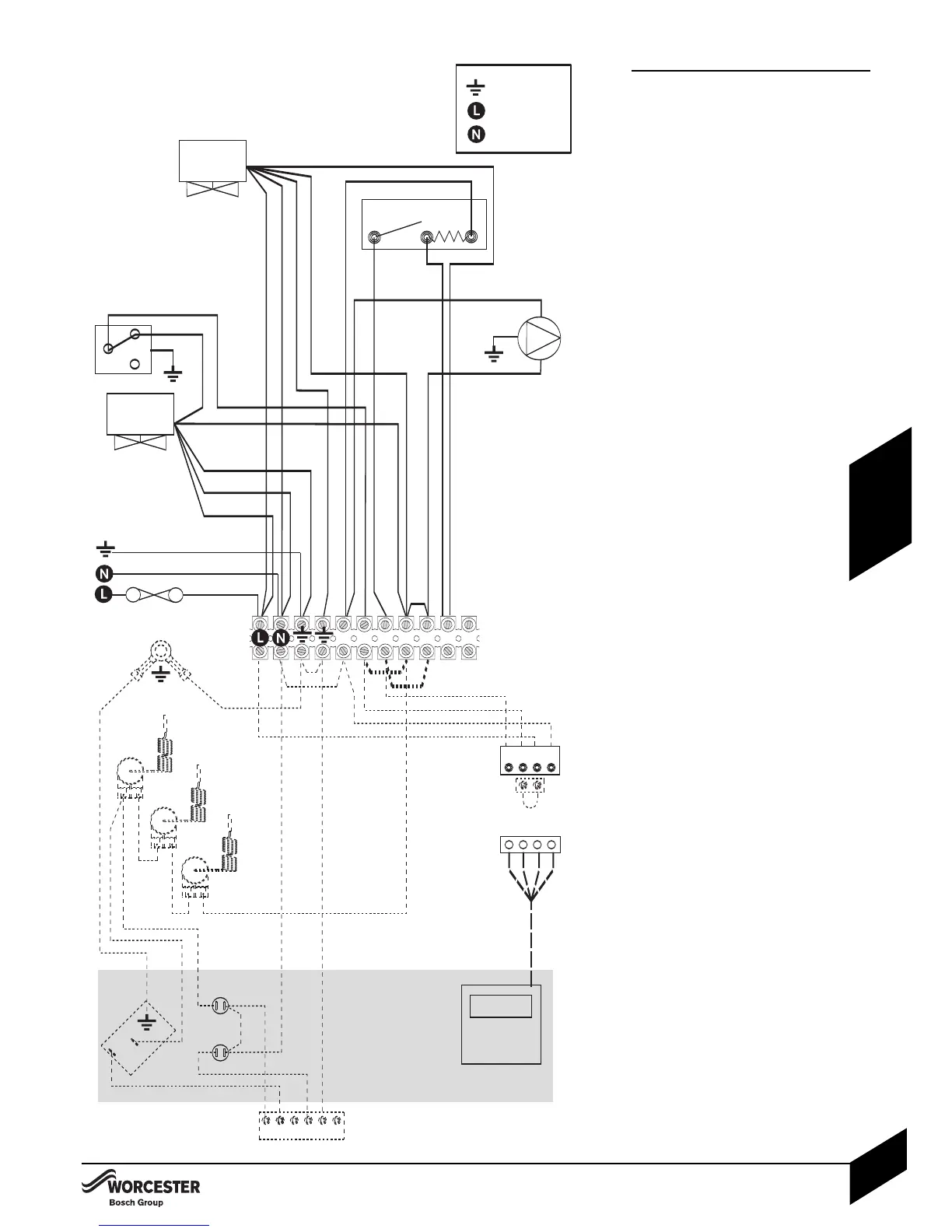
2 PORT VALVE CONTROL SET:
Key to components:
Q - CH ZONE VALVE.
R - ROOM THERMOSTAT.
S - CIRCULATING PUMP.
F - INTERNAL PROGRAMMER CONNECTOR.
G-TERMINAL CONNECTOR BLOCK.
H - LINK CONNECTOR.
T - HOT WATER CYLINDER THERMOSTAT.
U - HOT WATER VALVE.
P - OPTIONAL 230V WORCESTER
PROGRAMMER (fitted into fascia panel).
Terminator connector block (G):
4Remove link 1 to 3.
4Remove link 2 to 4.
4Make link 3 to 4.
Optional 230V Worcester (P):
4Set the pin on the rear of the programmer to
‘pumped’.
4Remove the link plug (H).
4Connect the plug from programmer (P) into
connector (F).