ELECTRICS
E
LE
CTRICS
I
N
S
TALLATION & SERVICING INSTRUCTIONS FOR WORCESTER GREENSTAR CAMRAY KITCHEN 12/18-18/25-25/32
8 716 113 000a (01/07)
26
INSTALLATION
DANGER - 230V:
ISOLATE THE MAINS ELECTRICITY
SUPPLY BEFORE STARTING ANY
WORK AND OBSERVE ALL RELEVANT
SAFETY PRECAUTIONS.
IMPORTANT: OBSERVE ELECTRONIC
STATIC DISCHARGE PRECAUTIONS.
DO NOT TOUCH THE PCB CIRCUITS.
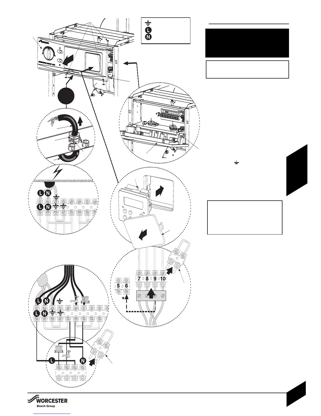
Access to 230V connections:
14Remove the four fascia retaining screws (A)
and position the fascia assembly (B) on the
two fascia location lugs (C) as shown.
24Release screws (D) from cable clamp (E).
4Feed sufficient power cable (F) through the
cable clamp (
E) and secure grip with screws (D).
4Separate wires from cable end and strip to 6mm.
230V connections:
34Connect LIVE wire (Brown) to
terminal L.
4Connect NEUTRAL wire (Blue) to
terminal N.
4Connect EARTH wire (Green/Yellow) to
the terminal .
Route the power cable down the side panel
using the clip provided on the support panel
to the external connection point avoiding any
potentially hot surfaces allowing sufficient
cable to pivot the control box into the service
position.
Any external device connected to the
boiler must take its power supply from
the boiler only and must NOT have a
separate supply.
See the following pages of electrical
diagrams for details of different systems.
Extermal 230V programmer:
4 4Remove link (G).
4Connect wires as shown.
Optional Worcester 230V programmer:
5 4Remove blanking plate (
H
).
4Set the pin on the rear of the programmer
to ‘pumped’.
4Remove link (G).
4Clip programmer ( I ) into position and plug
into the terminal as shown.
Refit fascia panel:
4Refit fascia panel (B) to control box
and secure with screws (A).
*Move the orange wire from terminal 9 to
terminal 6 for a 3 port valve system
.