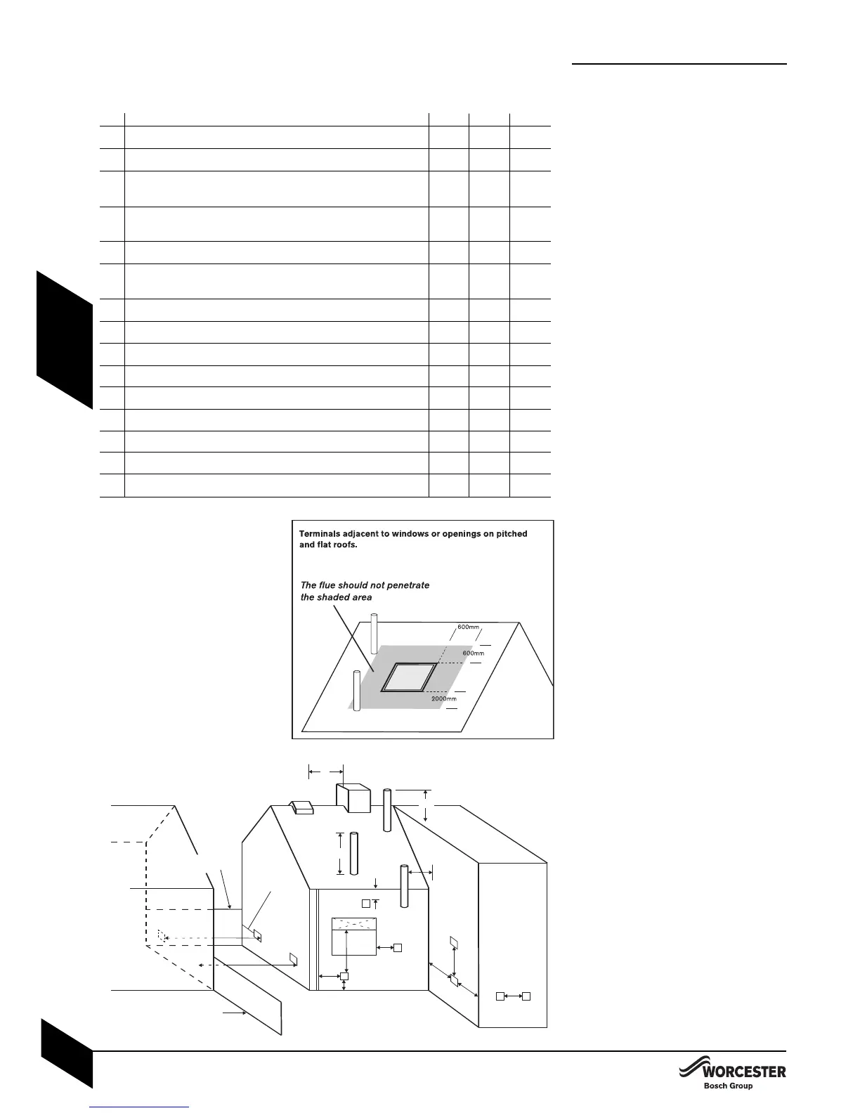
Minimum dimensions of flue terminal positions for oil-fired appliances:
TERMINAL POSITION CF RS(H) RS(V)
A
1 2
Directly below an opening, air brick, opening windows, etc N/A 600mm N/A
B
1 2
Horizontally to an opening, air brick, opening window, etc N/A 600mm N/A
C Below a plastic/painted gutter, drainage pipe or eaves if N/A 75mm N/A
combustible material protected
D
3
Below a plastic/painted gutter, drainage pipe or eaves without N/A 600mm N/A
protection to combustible material
E From vertical sanitary pipework N/A 300mm N/A
F From an external or internal corner or from a surface or boundry N/A 300mm N/A
alongside the terminal
G Above ground or balcony level N/A 300mm* N/A
H From a surface or boundary facing the terminal N/A 600mm** N/A
I From a terminal facing the terminal — 1200**mm —
J Vertically from a terminal on the same wall N/A 1500mm N/A
K Horizontally from a terminal on the same wall — 750mm —
L Above the point of highest intersection with the roof 600mm — 600mm
M From a vertical structure on the side of the terminal 750mm — 750mm
N Above a vertical structure less than 750mm from the side of the terminal 600mm — 600mm
O From a ridge terminal to a vertical structure on the roof 1500mm — N/A
— Not applicable
N/A Not allowed
CF Conventional flue
RS(H) Room Sealed Horizontal flue
RS(V) Room Sealed Vertical flue
1 An opening means an openable
element, such as an openable
window, or a permanent opening
such as a permanently open air vent
.
2 Notwithstanding the dimensions
above, a terminal should be at least
300mm from combustible material,
e.g. a window frame.
3 A way of providing protection of
combustible material w
ould be to fit
a heat shield at least 750mm wide.
FLUE TERMINAL POSITIONS
I
NSTALLATION & SERVICING INSTRUCTIONS FOR WORCESTER GREENSTAR CAMRAY KITCHEN 12/18-18/25-25/32
8 716 113 000a (01/07)
15
PRE -
INSTALLATION
F
LUE TERMINAL POSITIONS
• The flue must be fitted and terminated in
accordance with the recommendations of
BS 5410.
• Flue terminals must be positioned to avoid
combustion products entering into buildings.
• The flue must not cause an obstruction.
• Discharge from the flue outlet must not be a
nuisance.
• Flue gases have a tendency to plume and in
certain weather conditions a white plume of
condensation will be discharged from the flue
outlet which could be regarded as a
nuisance, for example, near security lighting.
• There should be no restriction preventing the
clearance of combustion products from the
terminal.
• The air inlet/outlet duct and the terminal of
the boiler must not be closer than 25mm to
any combustible material. Detailed
recommendations on protection of
combustible materials are given in BS 5410:1
• A protective terminal guard must be fitted if
the terminal is 2m or less above a surface
where people have access.
The guard must be spaced equally (minimum
50mm) around the flue and fixed to the wall
with plated screws
.
Stainless steet terminal guard:
Part No. 7 716 190 050.
• The following additional guidelines (from part
L Exceptions Guidance Document) are
recommended when determining the flue
outlet position:
• Avoid disc
harging flue gases into car ports
or narrow pass
ageways
.
• *Minimum distance of the flue terminal from
above ground is 2
1
00mm where directed to a
public footpath, private access route or a
frequently used area and 2500mm from a
car parking area
.
• **Minimum distance of the flue terminal to a
facing wall, fence, building or property
boundar
y is 2500mm.