I
N
SPECTION AND SERVICE
I
N
S
TALLATION & SERVICING INSTRUCTIONS FOR WORCESTER GREENSTAR CAMRAY KITCHEN 12/18-18/25-25/32
8 716 113 000a (01/07)
42
SERVICING
& SPARES
INSPECTION AND SERVICE
External oil filter:
4Remove the paper element from the external
oil filter and replace it. If the filter contains a
washable element, thoroughly clean in
kerosene and reassemble into the filter.
Clean the boiler:
Manifold access:
4Release screws (A) to remove the flue
manifold access cover (B) and remove any
debris.
4Check the condensate route (C) is clear and
clean the condensate trap and pipework.
4Check the flue system and clean if necessary.
4Remove the baffle retainer (D) and baffles (E)
from the secondary heat exchanger.
4Check and clean the secondary heat
exchanger surfaces.
NOTE: Do not use wire brushes and
cleaning agents to clean the stainless steel
components.
4Pour 500ml of water into drain (F) to refill the
condensate trap.
4Clean the secondar
y heat exchanger baffles
(E) if necessary and refit correctly.
4 Refit the baffle retainer (D).
4 Check the seal on the manifold access cover
(A) and replace if necessary.
4 Refit the flue manifold access cover (A) and
secure with screws (B).
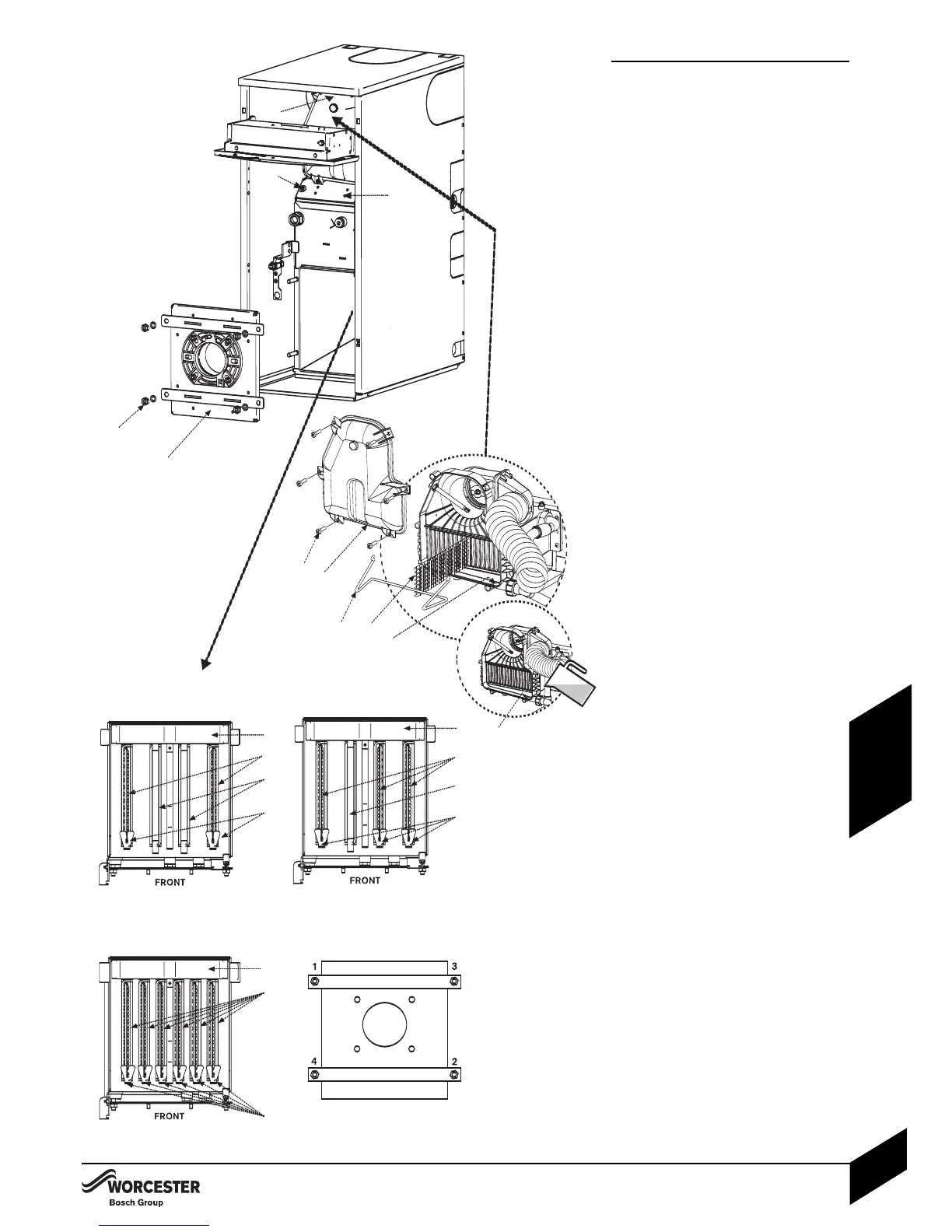
Combustion chamber:
4 Release the M10 retaining nuts and washers ( I )
and remove combustion chamber access door ( J ).
4Check the fibreglass rope seal on the
combustion chamber access door ( J ) and
replace if necessary.
4Remove the 2 screws (K) and baffle access
panel (L) located at the top of the primary heat
exchanger and check the baffle retainers (M).
4 Remove the baffles (N) and restrictor plate/s
(O, not on 25/32 model), clean and check
the condition of the baffles and the restrictor
plate/s. Replace any parts
considered to be
badly corroded/degraded.
4Remove the acoustic insulation insert (P).
4Thoroughly clean all of the heat exchanger
surfaces using a suitable brush and clear all
loose debris from the combustion c
hamber
and upper chamber.
4Check the condition of the combustion
c
hamber access door insulation
. If the
insulation is damaged the door assembly
must be replaced.
4Check the condition of the baffle access
panel seal.
4Replace the acoustic insulation insert (P).
4Refit the items in reverse order ensure the
baffles (N), baffle retainers (M) and restrictor
plate/s (O, not on 25/32 model) are correctly
fitted for the boiler output as shown in the
plan view opposite.
4Refit baffle access panel (L).
4Refit combustion chamber access door (J).
4Secure with nuts and washers ( I ) and
tighten until the door is firmly secured using
the sequence shown opposite. Do not over
tighten the nuts.
Fire valve:
4Check that the oil supply pipe has a fire valve
fitted externally to the building with the fire
valve sensor located within the
appliance case. A fire valve sensor clip (
Q) is
provided
for this purpose.