6 720 610 576 GB (03.02)
Installation regulations
11
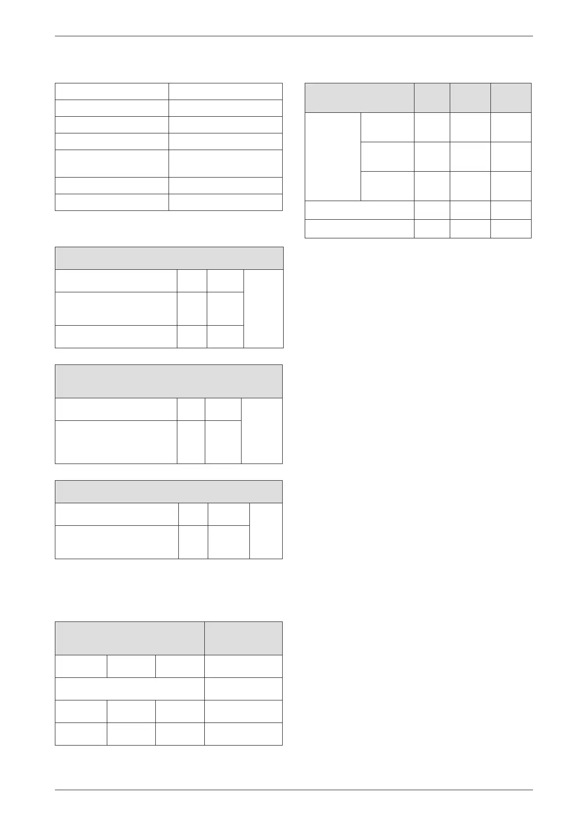
Condensate analysis, mg/l
Flue system
Elbow - 90 ° Equivalent length 2 m
Bend - 45 ° Equivalent length 1m
Gas supply
Domestic water performance
2 Installation regulations
Gas Safety (Installation & Use) Regulations 1998: All
gas appliances must be installed by a competent per-
son. Failure to install correctly could lead to prosecu-
tion.
The manufacturers notes must not be taken, in any way,
as overriding statutory obligations.
The appliance must be installed in accordance with the
current IEE Wiring Regulations, local Building Regula-
tions, Building Standards (Scotland) (Consolidation),
bye-laws of the local Water Company, Health and
Safety Document 635 (Electricity at Work Regulations
1989) and any other local requirements.
Product Liability regulations indicate that, in certain cir-
cumstances, the installer can be held responsible, not
only for mistakes on his part but also for damage result-
ing from the use of faulty materials. We advise the
installer to avoid any risk by using only quality approved
branded fittings.
The relevant British Standards should be followed i.e.
• BS 6798: Specification for the installation of gas
fired hot water boilers of rated input not exceeding
60kW
• BS 5449: Central Heating for Domestic Premises
• BS 5546: Installation of gas hot water supplies for
domestic purposes
• BS 5440:1: Flues and ventilation for gas appliances
of rated input not exceeding 70 kW (net): Flues
• BS 5440:2: Flues and ventilation for gas appliances
of rated input not exceeding 70 kW (net): Air
Supply
• BS 6891: Installation of low pressure gas pipework
installations up to 28mm (R1).
• BS 7074:1: Code of practice for domestic heating
and hot water supply
• BS 7671: Requirements for Electrical Installation.
These instructions must be followed.
Ammonium 1.2 Nickel 0.15
Lead ≤ 0.01 Mercury ≤ 0.0001
Cadmium ≤ 0.001 Sulphate 1
Chromium ≤ 0.005 Zinc ≤ 0.015
Halogenated
hydrocarbons ≤ 0.002
Tin ≤ 0.01
Hydrocarbons 0.015 Vanadium ≤ 0.001
Copper 0.028 pH-value 4.8
Table 4
HORIZONTAL 100 mm – Standard
Overall Diameter of Duct mm 100 Max.
4 m
Flue Terminal / Duct
Assembly Length
mm 600
Extension Duct Length mm 1000
Table 5
ALTERNATIVE HORIZONTAL 125 mm FLUE
SYSTEM
Overall Diameter of Duct mm 125 Max.
13 m
(inclu-
ding
turret)
Flue Terminal / Duct
Assembly
mm 1030
Table 6
VERTICAL 125 mm FLUE SYSTEM
Overall Diameter of Duct mm 125 Max.
15 m
Flue Terminal / Duct
Assembly
mm 1360
Table 7
Total length of gas supply pipe
(metres)
Pipe diameter
(mm)
369
Gas discharge rate (m
3
/h)
8.7 5.8 4.6 22
18.0 12.0 9.4 28
Table 8
ZWB
7-25
ZWB
7-30
Domestic
Water Flow
Rate l/min
Tempera-
ture Rise
30 °C 13.2 13.9
Tempera-
ture Rise
35 °C 11.3 11.9
Tempera-
ture Rise
40 °C 9.9 10.4
Maximum Mains pressure bar 10.0 10.0
Minimum Mains pressure bar 0.2 0.2
Table 9

 Loading...


