6 720 610 597 GB (03.02)
44
Maintenance
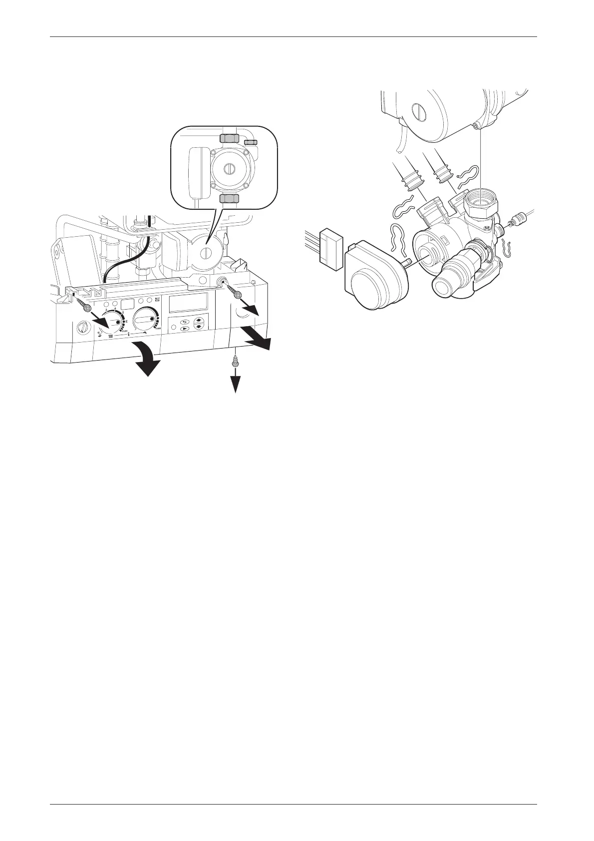
Alternatively
B After removing the siphon release the four Allen
screws and remove and replace the pump head.
Fig. 58
9.3.4 3-way diverter valve
B Switch off the appliance.
B Disconnect appliance from the power supply.
B Turn off service cocks.
B Unplug connector from 3-way valve motor. Refer to
fig. 59.
B Pull out retaining clip.
B Remove motor.
B Disconnect the relief valve drain.
B Disconnect the pressure gauge by withdrawing the
clip and pulling out the capillary head.
B Undo pipe unions by withdrawing the clips.
B Remove 3-way valve.
Fig. 59
After refitting:
B Fill system, bleed and re-pressurise
(see Installation Instructions).
9.3.5 3-way diverter valve motor
B Switch off the appliance.
B Turn off the service cocks.
B Unplug connector from 3-way valve motor. Refer to
fig. 59.
B Pull out retaining clip.
B Remove motor.
9.3.6 Sensors
B Check that the appliance is electrically isolated.
Central Heating Flow Temperature Sensor –
Item 36, fig. 2, 55
B Pull-off the connector.
B Release the sensor clip and withdraw the sensor.
B Apply heat transfer paste to the replacement sensor.
Safety Temperature Limiter – Item 6, fig. 2, 55
B Pull-off the connectors.
B Unscrew the sensor.
Flue Temperature Limiter – Item 9, fig. 2, 55
B Pull-off the connectors.
B Unscrew the sensor.
1.
1.
2.
3.
4.
5.
7 181 465 330-03.1R
7 181 465 330-12.1R

 Loading...


