6 720 610 597 GB (03.02)
18
Installation
3.9.1 Siting the Flue Terminal
The flue must be installed in accordance with
BS 5440:1 and the Building Regulations. Flue termi-
nals in carports and under balconies are to be avoided.
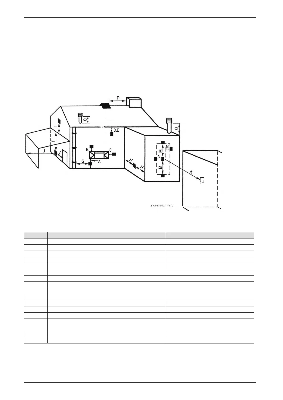
The terminal must be positioned so that it does not
cause an obstruction nor the combustion products a
nuisance. See fig. 15 and table 9.
The terminal will, at times, give out a plume of water
vapour and consideration must be given to this when
choosing a terminal position. Keep clear of security
lighting, activated by passive infra-red sensing heads.
If the terminal is less than 2 m above a surface to which
people have access then a guard must be fitted. The
guard must be evenly spaced about the terminal with a
space of 50 mm in each direction and fixed with plated
screws.
A guard Type K6 for the standard horizontal flue, can be
obtained from Tower Flue Components, Vale Rise, Ton-
bridge TN9 1TB.
Fig. 15
Minimum dimensions of flue terminal positions (all types) (see fig. 15)
Dimension Terminal Position (kW input expressed in net) Balanced flues room sealed: Fanned draught
A
1)
Directly below an opening, air brick, opening windows, etc. 300 mm
B
1)
Above an opening, air brick, opening window, etc. 300 mm
C
1)
Horizontally to an opening, air brick, opening window, etc. 300 mm
D Below gutters, soil pipes or drain pipes 75 mm
E Below eaves 200 mm
F
2)
Below balconies or car port roof (lowest point) 200 mm
G From a vertical drain pipe or soil pipe 150 mm
H From an internal or external corner 300 mm
I Above ground roof or balcony level 300 mm
J From a surface facing the terminal 600 mm
K From a terminal facing the terminal 1200 mm
L From an opening in the car port (e. g. door, window) into the dwelling 1200 mm
M Vertically from a terminal on the same wall 1500 mm
N Horizontally from a terminal on the same wall 300 mm
O From the wall on which the terminal is mounted Not applicable
P From a vertical structure on the roof Not applicable
Q Above intersection with roof Not applicable
Table 9
1) In addition, the terminal should not be nearer than 150 mm (fanned draught) to an opening in the building fabric formed for the purpose of accommo-
dating a built-in element such as a window frame.
2) Not recommended.
 Loading...


