6 720 610 597 GB (03.02)
Maintenance
45
Domestic Hot Water Temperature Sensor –
Item 6.1, fig. 2
B Check that the inlet water valve is closed and the
domestic hot water circuit is drained.
B Release and pull-off the connector.
B Unscrew the sensor.
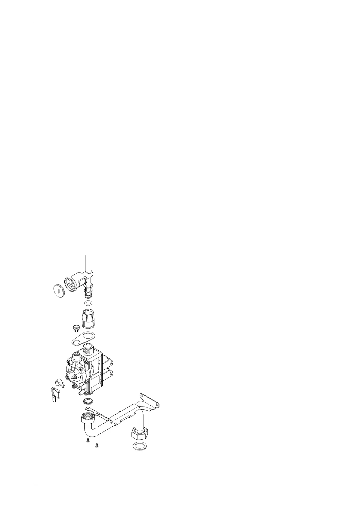
9.3.7 Gas Valve
B Check that the gas cock is turned off.
B Lower the control panel. Refer to fig. 58.
B Pull off the solenoid connections at the rear of the
valve.
B Undo the union, within the inner casing, securing the
valve to the gas/air tube. Refer to fig. 57.
B Remove the white plastic cap from the gas valve.
B Release the gas inlet union at the manifold assembly.
B Unscrew the two screws securing the gas valve
assembly bracket to the back panel and withdraw the
assembly.
B Transfer the bracket and inlet pipe assembly to the
new gas valve.
B Check for gas soundness when the new gas valve
has been fitted.
B Recheck the combustion performance as described
in section 8.1.
Fig. 60
9.3.8 Domestic Hot Water Heat Exchanger
B Refer to section 9.2.
B Use new seals when fitting the new heat exchanger.
9.3.9 Electrode assembly
B Refer to section 9.2.
B Use a new seal if the existing seal is damaged.
9.3.10 Pressure gauge
B Drain the appliance.
B Lower the facia. Refer to fig. 58.
B Twist the pressure gauge head anti-clockwise to
release it from the casing. Refer to fig. 2.
B Disconnect the capillary head from the rear of the
diverter valve by withdrawing the clip and pulling out
the head. Refer to fig. 59.
9.3.11 Expansion vessel
B Drain the appliance.
B Undo the union connection at the base of the vessel.
Refer to fig. 2.
B Unscrew the top and bottom fixing screws and
remove the vessel.
B Set the pressure of the new vessel to that required
by the system.
9.3.12 Pressure Relief Valve
B Drain the appliance.
B Disconnect the drain pipe from the valve. Refer to
fig. 30.
B Pull-out the clip securing the valve.
B Pull-out the valve.
B Ensure that the replacement valve is fully entered
before fitting the clip.
9.3.13 Burner
B Refer to section 9.2.
6 720 610 602 - 04.1O

 Loading...


