6 720 610 576 GB (03.02)
8
Details of the appliance
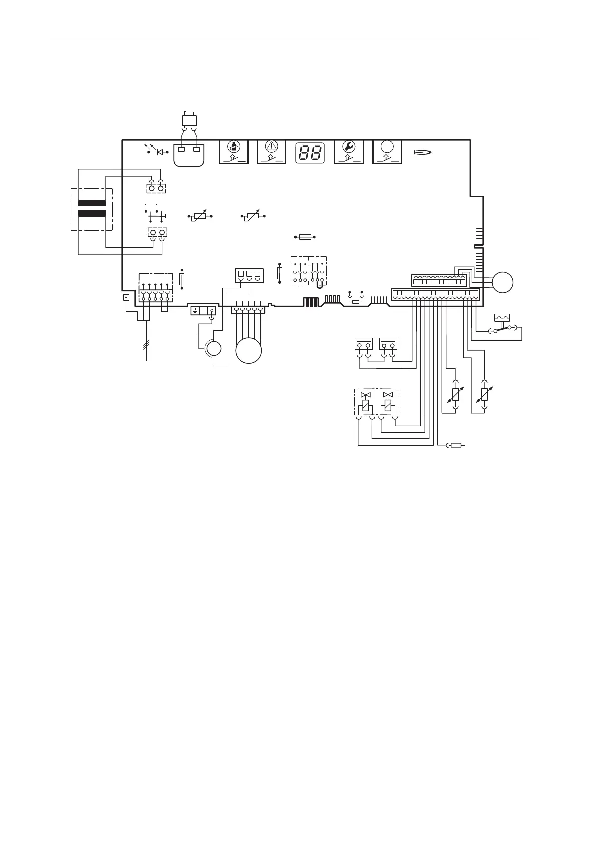
1.8 Electrical wiring diagram
Fig. 4
4.1 Ignition transformer
6 Temperature limiter, heat exchanger
6.1 Hot water NTC sensor
9 Flue gas temperature limiter
18 Pump
32 Flame sensing electrode
33 Ignition electrode
36 Temperature sensor in CH flow
52 Solenoid valve 1
52.1 Solenoid valve 2
56 Gas valve CE 427
61 Reset button
84 Motor, 3-way valve
96 Microswitch, hydraulic switch
135 Master switch
136 Temperature control for CH flow
151 Fuse, slow 2.5 A, AC 230 V
153 Transformer
161 Link
226 Fan
300 Code plug
302 Earth connection
310 Temperature control for hot water
312 Fuse, slow T 1,6 A
313 Fuse, slow T 0,5 A
314 Connector for programmer
315 Terminal block for programmer
317 Digital display
318 Connector for timer
328 Terminal block for AC 230 V Mains supply
328.1 Link
363 Indicator lamp for burner
364 Indicator lamp for power supply
365 “Chimney sweep” button
366 Service button
367 ECO button
6
9
32
33
36
52.1
52
56
61
230 V
135
25 V
230V/AC
153
136
151
12
4
7
89
315
161
M
226
300
L
NLs
Ns
328
LR
302
310
312
313
314
317
318
363
364
365
366
ECO
367
4.1
328.1
M
6.1
18
96
84
M
6 720 610 576-08.2O
mains supply
r
r
bl
bl
bl
bl
bl
o
o
o
o
g
g
p
p
p
o - orange g - green bl - black r - red p - purple

 Loading...


