DC Wiring
976-0043-01-02 3–15
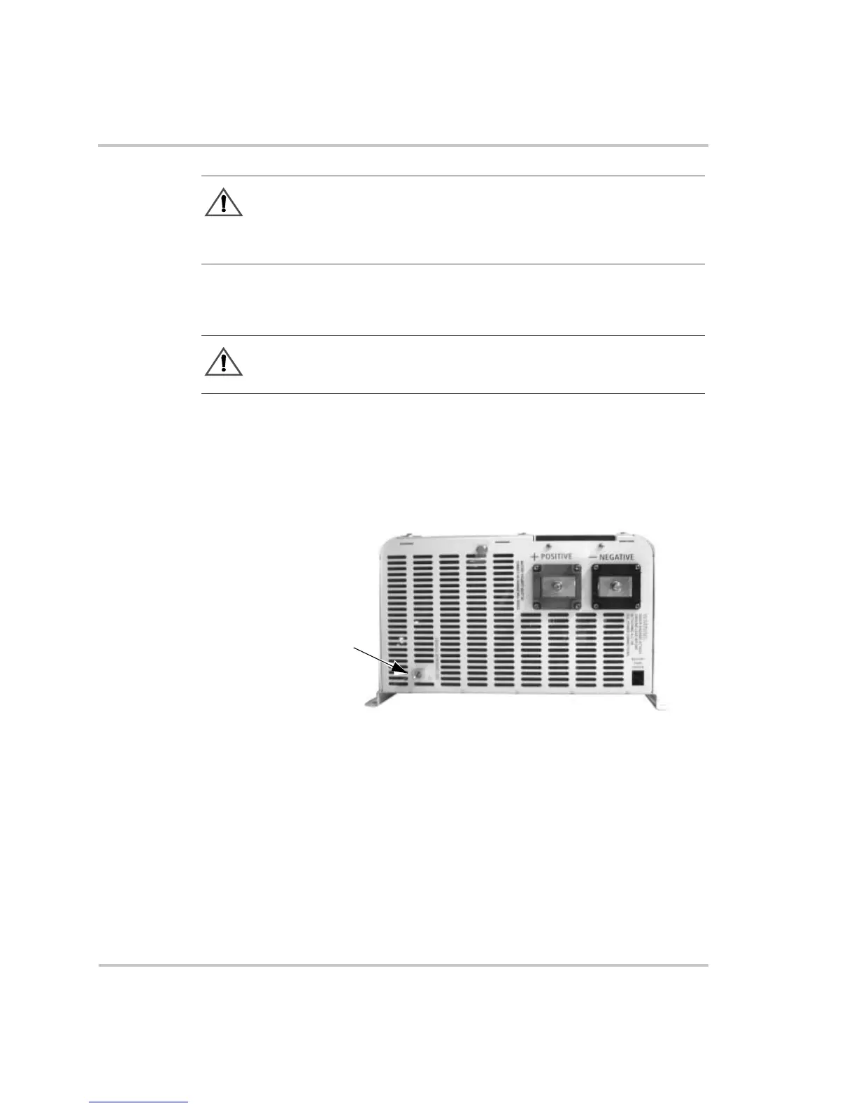
Grounding the DC System
The inverter’s chassis ground lug (see Figure 3-6) is used to connect the
chassis of the inverter to the DC grounding system. The terminal accepts
wires from #14 AWG to #2 AWG.
The Xantrex DC175 and DC250 have optional grounding blocks to
simplify grounding procedures and can be used as the DC disconnect as
shown in Figure 3-7 on page 3–16.
WARNING: Fire Hazard
Undersized cables can overheat and melt creating a fire hazard when subjected to
heavy (peak) loads. Always use a properly sized cable and length rated for the
amperage of the inverter and batteries.
WARNING: Shock Hazard
Always attach ground leads before attaching AC or DC power connections.
Figure 3-6
Chassis Ground Lug Location on Inverter DC End
Chassis
Ground Lug
DC End of Inverter
 Loading...