Repairs/Adjustments
4-6 09/06 PHASER 3124 / PHASER 3125
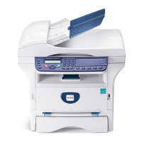
4. Use a flat bladed screwdriver to gently pry
the rear cover open, Figure 4.
Figure 4
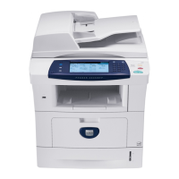
5. Remove the rear cover while disconnect-
ing CN2 (Phaser 3124) / CN 6 (Phaser
3125) from the main PBA, Figure 5.
Figure 5
Replacement
Replacement is the reverse of the removal
procedure.
REP 4 Top Cover Assembly
Parts list on PL 1
WARNING
Switch off the electricity to the machine. Dis-
connect the power cord from the customer
supply while performing tasks that do not
need electricity. Electricity can cause death or
injury. Moving parts can cause injury.
1. Remove the front cover assembly (refer to
REP 1).
2. Remove the rear cover (refer to REP 3).
3. Remove the toner cartridge.
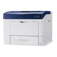
4. Remove 2 screws, Figure 1.
Figure 1