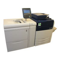
Installation Xerox
®
Versant™ 2100 Press
Customer Expectation and Installation Guide Xerox Confidential 34
Floor Information
Floor Specifications
The installation site floor must meet certain specifications and
requirements before the system is installed:
The customer must ensure and approve the floor composition and
strength.
The surface of the floor should be a hard, non-compressible surface such
as bare concrete, wood, or industrial grade floor tile. If the surface is
compressible/covered (for example, carpets or non-industrial tile), the
covering should be removed under the press.
Mobility (floor) plates are required for any installation occurring on
carpeting.
Additionally, mobility assist devices (supplied by the customer), such as
masonite or plywood, must be used for installations occurring on
ceramic tiles, uneven floors (which meet required specifications), or
carpeting. The mobility assist devices will ensure that the flooring is not
damaged during the installation process.
Floor Requirements
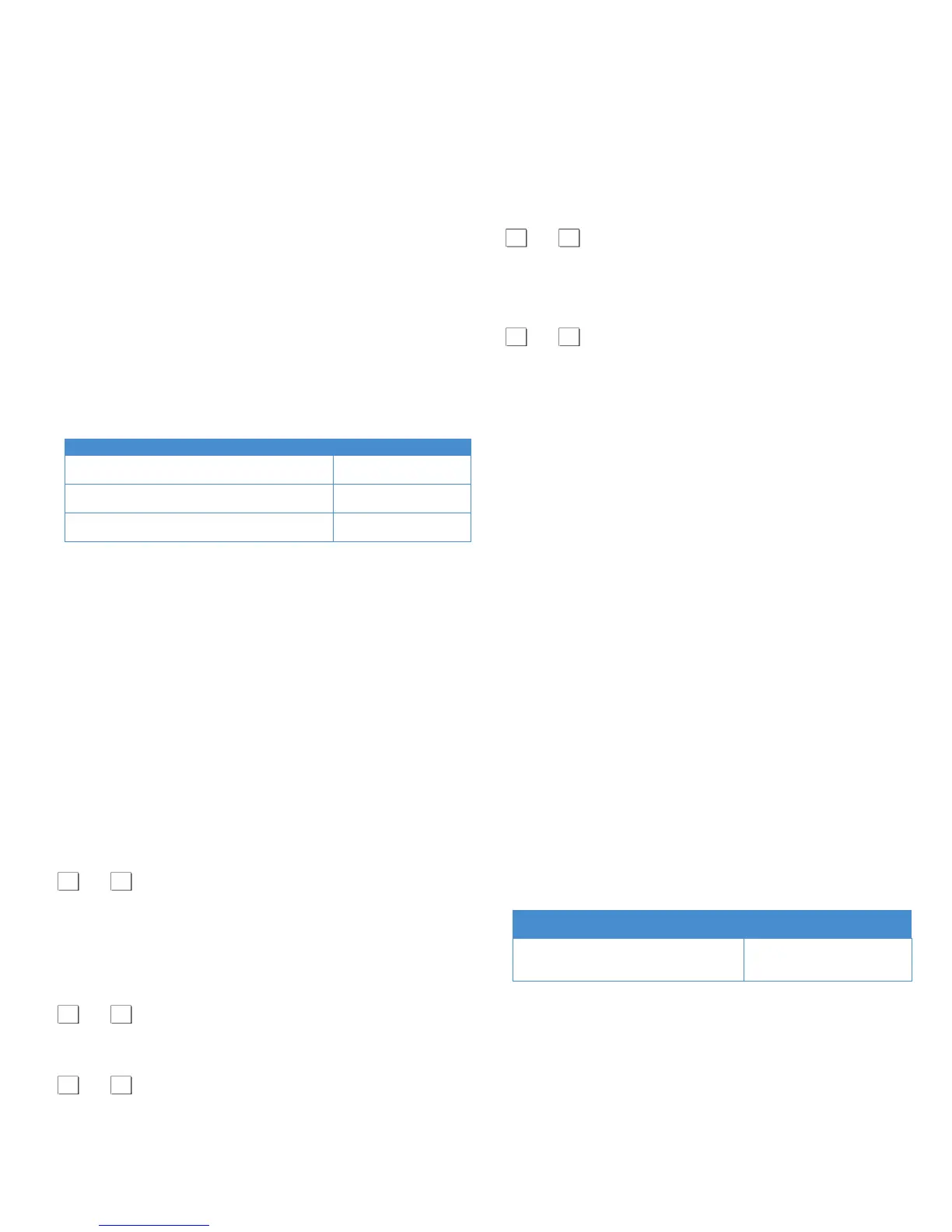
The following table lists the floor readiness activities and the person
responsible for completing that activity.
Activity Responsible Person
Certify the floor strength from the loading dock
to the installation site
Customer (and
structural engineer)
Certify the floor strength and composition for
the installation site
Customer (and
structural engineer)
Certify or remove
loor covering under press
location (if applicable)
Customer (and
structural engineer)
Floor Strength Information
As part of the structural inspection process, a structural engineer should
inspect and approve the site where the system will be installed.
The customer site floor must safely support the weight of the entire press
and all its components. This includes the weight of all optional feeding and
finishing devices that the customer intends to add. Therefore, the
structural engineer and customer must evaluate and calculate the weight of
all the modules and optional accessories (including any third-party
finishing devices) in order to accurately determine the appropriate floor
strength and weight distribution needed at the installation site.
For product specification information on all third-party finishing devices,
refer to the specific third-party customer documentation.
Floor Worksheets
Floors/Floor Coverings Worksheet
Are the floors or floor coverings along the delivery route concrete or
industrial tile?
Yes No
If No: Customer must supply Carriers with hardboard/plywood or metal
plates/Masonite for rolling the press over the floors that are not concrete
or industrial tile.
Raised Floors Worksheet
Are there any raised floors on the delivery route?
Yes No
If Yes: Has a structural engineer or the customer signed off/approved that
the floors meet requirements?
Yes No
If No: Sign off/Approval is required.
NOTE: Carriers MUST lift all the raised-floor tiles on the route to ensure
the support structure integrity.
NOTE: Carriers will use hardboard or metal plates (such as masonite or
plywood) when rolling the press over the raised floor.
Floor Strength/Load Worksheet
Has a structural engineer or the customer signed off/approved that the
floor meets requirements?
Yes No
If No: Sign off/Approval is required.
Is the floor of the pathway route and destination area able to hold the
combined weight of the press left and right modules (1,248 lb./566.1 kg)?
Yes No
If No: An alternative route/destination site must be considered.
Mobility Plate Information
Mobility Plates
All installations occurring on carpeted flooring surfaces require the
installation of a mobility plate to allow the product to be moved during
normal maintenance.
Mobility plates are available from your Sales Representative.
Mobility Plate Kit
Part number: 497K5270 is the only mobility plate kit that is available for
the press and its optional feeding/finishing devices. The kit includes the
following contents:
1 Plate
4 Bracket assemblies
8 Nuts
1 set of kit instructions
Each plate is:
19.68 in./500 mm (width) x 29.52 in./750 mm (depth)
0.12 in./3 mm (thickness)
19 lb./8.6 kg
Optional kits must be ordered for any optional feeding/finishing devices
that are attached to the press. Refer to the next section in this guide for
specific information on each feeding/finishing device.
Mobility Plate Charts
The following tables show the number of mobility plates required for the
base configuration and for the various optional feeding and finishing
devices.
Base Configuration
Module name
Required number of kits
Press (Advance HFC + Left and Right
modules)
5 kits (3 for the left and right
modules and; 2 for the
Advanced HCF)
Optional Devices Chart
The following table lists the number of ADDITIONAL plates required
for the various optional devices. The number of plates listed does not
include the base press (left and right modules and Advanced HCF).
NOTE: The Interface Module is required with any system configuration that
has one or more finishing device, except the Offset Catch Tray (OCT).
 Loading...