KC705 Evaluation Board 109
UG810 (v1.8) March 20, 2018 www.xilinx.com
Appendix D
Board Setup
Installing KC705 Board in a PC Chassis
Installation of the KC705 board inside a computer chassis is required when developing or
testing PCI Express functionality.
When the KC705 board is used inside a computer chassis (i.e., plugged in to the PCIe® slot),
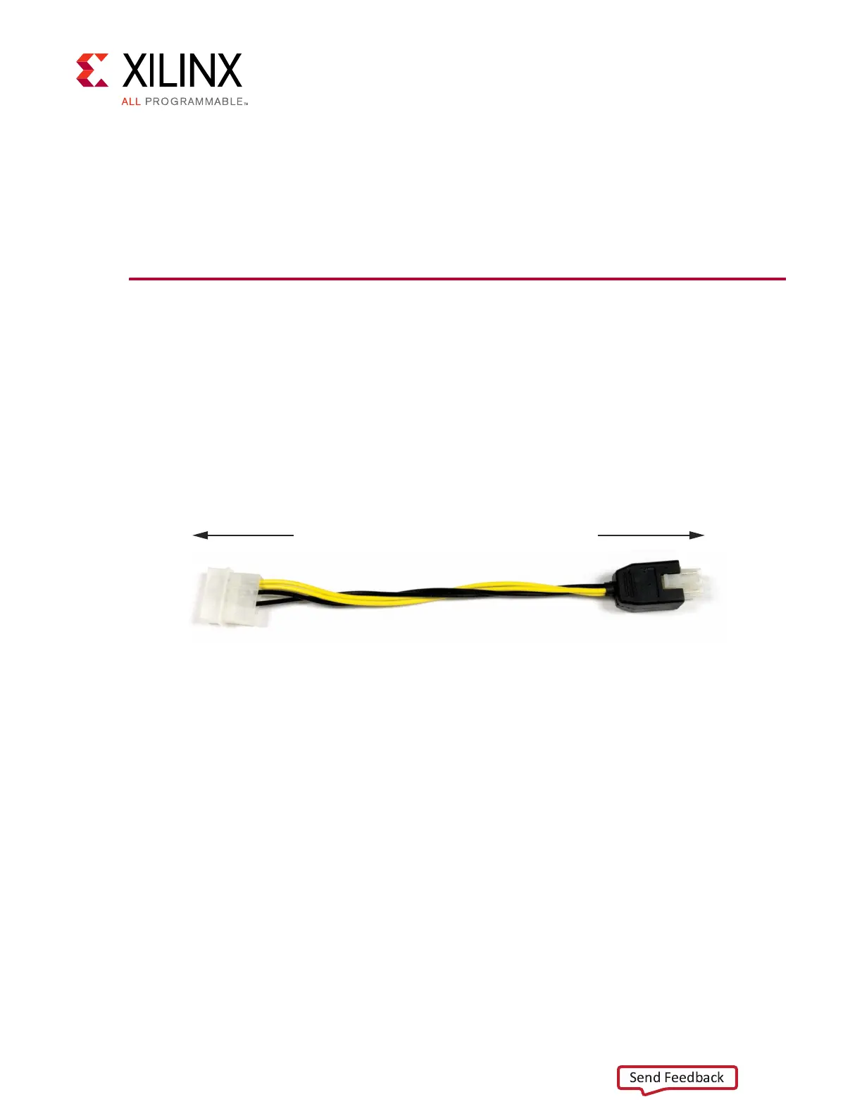
power is provided from the ATX power supply 4-pin peripheral connector through the ATX
adapter cable shown in Figure D-1 to J18 on the KC705 board. The Xilinx part number for
this cable is 2600304 and is equivalent to Sourcegate Technologies part number
AZCBL-WH-1109-RA4. For information on ordering this cable, see [Ref 20].
To install the KC705 board in a PC chassis:
1. On the KC705 board, remove the six screws retaining the six rubber feet with their
standoffs, and the PCIe bracket. Reinstall the PCIe bracket using two of the previously
removed screws.
2. Power down the host computer and remove the power cord from the PC.
3. Open the PC chassis following the instructions provided with the PC.
4. Select a vacant PCIe expansion slot and remove the expansion cover (at the back of the
chassis) by removing the screws on the top and bottom of the cover.
5. Plug the KC705 board into the PCIe connector at this slot.
6. Install the top mounting bracket screw into the PC expansion cover retainer bracket to
secure the KC705 board in its slot.
Note:
The KC705 board is taller than standard PCIe cards. Ensure that the height of the card is
free of obstructions.
X-Ref Target - Figure D-1
Figure D-1: ATX Power Supply Adapter Cable
UG810_aD_01_031214
To ATX 4-Pin Peripheral
Power Connector
To J49 on KC705 Board