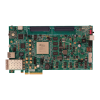
KC705 Evaluation Board 68
UG810 (v1.8) March 20, 2018 www.xilinx.com
Chapter 1: KC705 Evaluation Board Features
LPC Connector J2
[Figure 1-2, callout 31]
The 160-pin LPC connector defined by the FMC specification (Figure B-2, page 87) provides
connectivity for up to:
• 68 single-ended or 34 differential user-defined signals
•1 GTX transceiver
•1 GTX clock
• 2 differential clocks
• 61 ground and 10 power connections
The connections between the LPC connector at J2 and FPGA U1 (Table 1-29) implement a
subset of this connectivity:
• 34 differential user defined pairs
°
34 LA pairs (LA00-LA33)
•1 GTX transceiver
•1 GTX clock
J21 FMC_HPC_HA22_P LVDS L11 K20 FMC_HPC_HA21_N LVDS J12
J22 FMC_HPC_HA22_N LVDS K11 K22 FMC_HPC_HA23_P LVDS L12
J24 NC K23 FMC_HPC_HA23_N LVDS L13
J25 NC K25 NC
J27 NC K26 NC
J28 NC K28 NC
J30 NC K29 NC
J31 NC K31 NC
J33 NC K32 NC
J34 NC K34 NC
J36 NC K35 NC
J37 NC K37 NC
J39 NC K38 NC
K40 NC
Table 1-28: HPC Connections, J22 to FPGA U1 (Cont’d)
J22 Pin Schematic Net Name
I/O
Standard
FPGA
U1 Pin
J22 Pin Schematic Net Name
I/O
Standard
FPGA
U1 Pin
 Loading...


