KC705 Evaluation Board 57
UG810 (v1.8) March 20, 2018 www.xilinx.com
Chapter 1: KC705 Evaluation Board Features
CPU Reset Pushbutton
[Figure 1-2, callout 37]
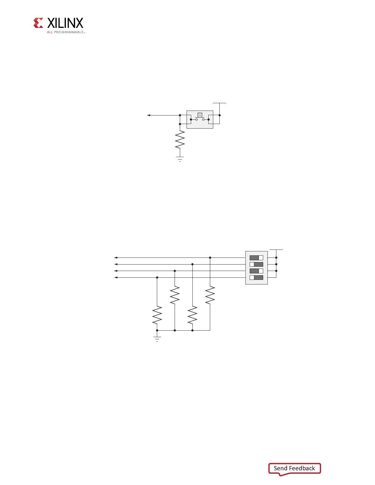
Figure 1-27 shows the CPU reset pushbutton circuit.
GPIO DIP Switch
[Figure 1-2, callout 24]
Figure 1-28 shows the GPIO DIP Switch circuit.
X-Ref Target - Fig ure 1-27
Figure 1-27: CPU Reset Pushbutton
UG810_c1_27_031214
VCC1V5
CPU_RESET
R15
4.7kΩ
0.1 W
5%
GND
4
32
1
SW7
X-Ref Target - Figure 1-28
Figure 1-28: GPIO DIP Switch
UG810_c1_28_031214
SDA04H1SBD
SW11
VADJ
GPIO_DIP_SW3
GPIO_DIP_SW2
GPIO_DIP_SW1
GPIO_DIP_SW0
R25
4.7kΩ
0.1 W
5%
R24
4.7kΩ
0.1 W
5%
R23
4.7kΩ
0.1 W
5%
R22
4.7kΩ
0.1 W
5%
1
2
3
4
8
7
6
5
GND