KC705 Evaluation Board 55
UG810 (v1.8) March 20, 2018 www.xilinx.com
Chapter 1: KC705 Evaluation Board Features
°
GPIO_SW_[NESWC]: SW2, SW3, SW4, SW6, SW5
°
CPU_RESET: SW7
• 4-position user DIP Switch (callout 24)
°
GPIO_DIP_SW[3:0]: SW11
• User Rotary Switch (callout 25, hidden beneath the LCD)
°
ROTARY_PUSH, ROTARY_INCA, ROTARY_INCB: SW8
• User SMA (callout 26)
°
USER_SMA_GPIO_P, USER_SMA_GPIO_N: J13, J14
• 2 line x 16 character LCD Character Display (callout 19)
°
If the display is unmounted, connector J31 pins are available as 7 independent 5V
GPIOs
User GPIO LEDs
[Figure 1-2, callout 34]
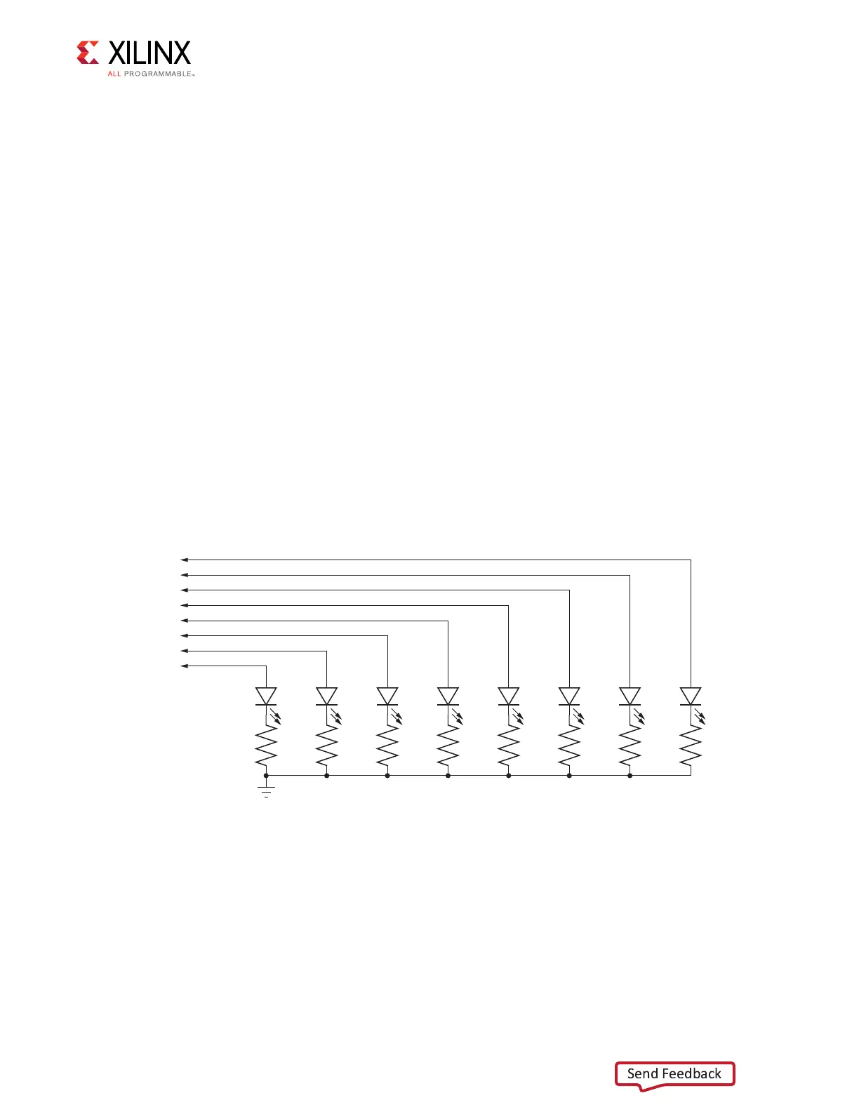
Figure 1-25 shows the user LED circuits.
X-Ref Target - Figure 1-25
Figure 1-25: User LEDs
UG810_c1_25_031214
R93
49.9Ω
1%
DS4
R94
49.9Ω
1%
DS1
R95
49.9Ω
1%
DS10
R96
49.9Ω
1%
DS2
R97
49.9Ω
1%
DS3
R440
49.9Ω
1%
DS25
R441
49.9Ω
1%
DS26
R442
49.9Ω
1%
GND
DS27
GPIO_LED_6
GPIO_LED_4
GPIO_LED_5
GPIO_LED_2
GPIO_LED_0
GPIO_LED_1
GPIO_LED_3
GPIO_LED_7