ML505/ML506/ML507 Evaluation Platform www.xilinx.com 21
UG347 (v3.1.1) October 7, 2009
Detailed Description
R
7. User and Error LEDs (Active-High)
There are a total of 15 active-High LEDs directly controllable by the FPGA:
• Eight green LEDs are general purpose LEDs arranged in a row
• Five green LEDs are positioned next to the North-East-South-West-Center-oriented
pushbuttons (only the center one is cited in Figure 1-2, page 15)
• Two red LEDs are intended to be used for signaling error conditions, such as bus
errors, but can be used for any other purpose
Some LEDs are buffered through the CPLD to allow the LED signals to be used as higher-
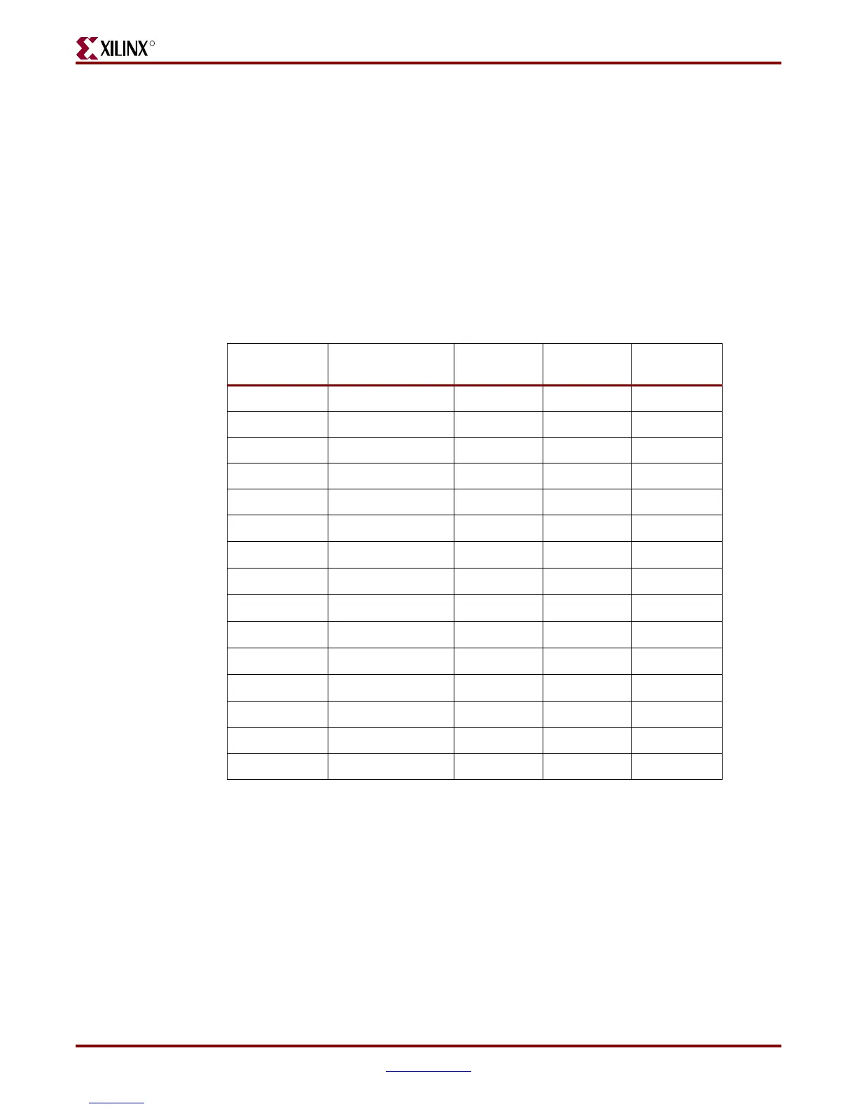
performance I/O by way of the XGI expansion connector. Table 1-6 summarizes the LED
definitions and connections.
Table 1-6: User and Error LED Connections
Reference
Designator
Label/Definition Color FPGA Pin Buffered
DS20 LED North Green AF13 Yes
DS21 LED East Green AG23 Yes
DS22 LED South Green AG12 Yes
DS23 LED West Green AF23 Yes
DS24 LED Center Green E8 Yes
DS17
GPIO LED 0 Green
H18
Yes
DS16
GPIO LED 1 Green
L18
Yes
DS15
GPIO LED 2 Green
G15
Yes
DS14
GPIO LED 3 Green
AD26
No
DS13
GPIO LED 4 Green
G16 Yes
DS12
GPIO LED 5 Green
AD25 No
DS11
GPIO LED 6 Green
AD24 No
DS10
GPIO LED 7 Green
AE24 No
DS6 Error 1 Red F6 No
DS6 Error 2 Red T10 No
Downloaded from Elcodis.com electronic components distributor