44 www.xilinx.com ML505/ML506/ML507 Evaluation Platform
UG347 (v3.1.1) October 7, 2009
Chapter 1: ML505/ML506/ML507 Evaluation Platform
R
41. Serial-ATA Host Connectors
Serial-ATA (SATA) is the next generation of the ATA interface used for storage devices
such as hard disks. The board contains two SATA host connectors that can be connected to
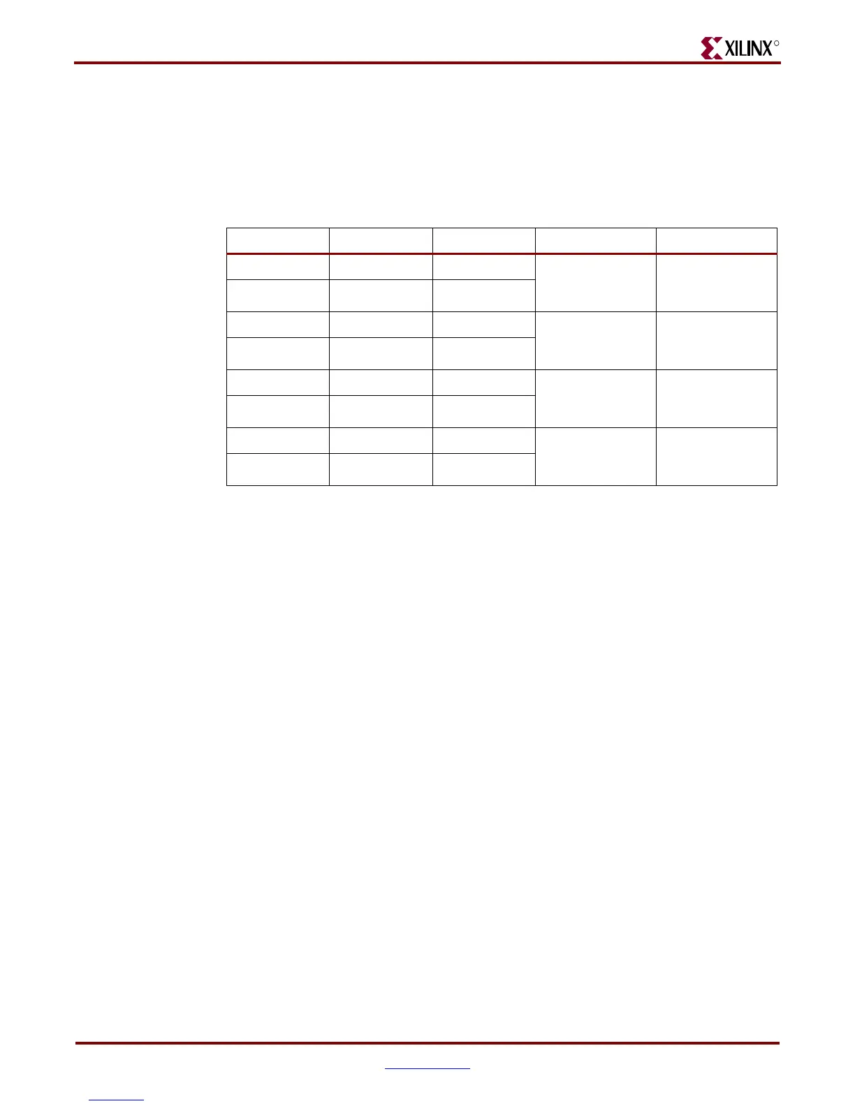
a SATA device (such as a hard disk) using a standard SATA cable. The SATA connectors
are connected to GTPs on the FPGA as shown in Table 1-26.
SATA can also be used as a convenient and low cost medium for connecting GTP/GTX
transceivers. The SATA physical interface can carry GTP/GTX signals up to 1.5 Gb/s for
general-purpose usage. The board ships with a special Xilinx SATA crossover cable that is
used as a loopback connection between the two SATA host connectors for loopback testing
and bit error rate testing (BERT). The SATA crossover cable can also be used to connect
GTP/GTX transceivers between two boards. For GTP/GTX SATA clock jumpering, see
Figure 1-4, page 32.
Note:
The special SATA crossover cable cannot be used to connect a SATA host to a SATA device
(that is, PC to hard disk). It is only intended for host-to-host loopback connections.
42. SFP Connector
The board contains a small form-factor pluggable (SFP) connector and cage assembly that
accepts SFP modules. The SFP interface is connected to GTP0 of GTP_X0Y4 on the FPGA.
The SFP module serial ID interface is connected to the IIC multiplexer on the board (See
“14. IIC Bus with 8-Kb EEPROM,” page 27 for more information). The control and status
signals for the SFP module are connected to jumpers, test points, and LEDs as described in
Table 1-27. The SFP module connections are shown in Table 1-28, page 45.
Table 1-26: SATA Connections
Pin Name FPGA Pin (U1) Connector Pin ML505/ML506 ML507
SATA1_RX_P W1 J40, pin 6 GTP0 of
GTP_X0Y2
receive pair
GTX0 of
GTX_X0Y3
receive pair
SATA1_RX_N Y1 J40, pin 5
SATA1_TX_P V2 J40, pin 2 GTP0 of
GTP_X0Y2
transmit pair
GTX0 of
GTX_X0Y3
transmit pair
SATA1_TX_N W2 J40, pin 3
SATA2_RX_P AB1 J41, pin 6 GTP1 of
GTP_X0Y2
receive pair
GTX1 of
GTX_X0Y3
receive pair
SATA2_RX_N AA1 J41, pin 5
SATA2_TX_P AC2 J41, pin 2 GTP1 of
GTP_X0Y2
transmit pair
GTX1 of
GTX_X0Y3
transmit pair
SATA2_TX_N AB2 J41, pin 3
Downloaded from Elcodis.com electronic components distributor