28 www.xilinx.com ML505/ML506/ML507 Evaluation Platform
UG347 (v3.1.1) October 7, 2009
Chapter 1: ML505/ML506/ML507 Evaluation Platform
R
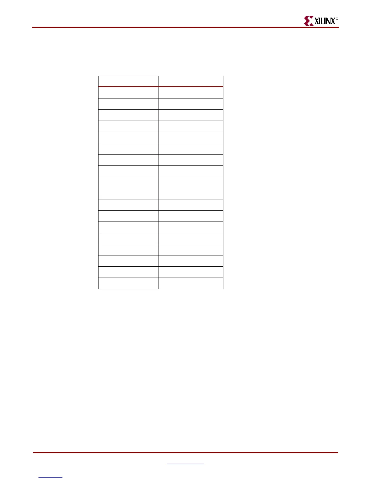
The DVI connector (Table 1-14) supports the IIC protocol to allow the board to read the
monitor’s configuration parameters. These parameters can be read by the FPGA using the
VGA IIC bus.
16. PS/2 Mouse and Keyboard Ports
The board contains two PS/2 ports: one for a mouse (P5) and the other for a keyboard (P4).
Bidirectional level shifting transistors allow the FPGA's 1.8V I/O to interface with the 5V
I/O of the PS/2 ports. The PS/2 ports on the board are powered directly by the main 5V
power jack, which also powers the rest of the board.
Caution!
Care must be taken to ensure that the power load of any attached PS/2 devices does
not overload the AC adapter.
17. System ACE and CompactFlash Connector
The Xilinx System ACE CompactFlash (CF) configuration controller allows a Type I
CompactFlash card to program the FPGA through the JTAG port. Both hardware and
software data can be downloaded through the JTAG port. The System ACE controller
supports up to eight configuration images on a single CompactFlash card. The
configuration address switches allow the user to choose which of the eight configuration
images to use.
Table 1-14: DVI Controller Connections
Net Name FPGA Pin
DVI_D[0] AB8
DVI_D[1] AC8
DVI_D[2] AN12
DVI_D[3] AP12
DVI_D[4] AA9
DVI_D[5] AA8
DVI_D[6] AM13
DVI_D[7] AN13
DVI_D[8] AA10
DVI_D[9] AB10
DVI_D[10] AP14
DVI_D[11] AN14
DVI_XCLK_P AL11
DVI_XCLK_N AL10
DVI_HSYNC AM12
DVI_VSYNC AM11
DVI_DE AE8
DVI_RESET_B AK6
Downloaded from Elcodis.com electronic components distributor