RocketIO™ Transceiver User Guide www.xilinx.com 113
UG024 (v3.0) February 22, 2007
PCB Design Requirements
R
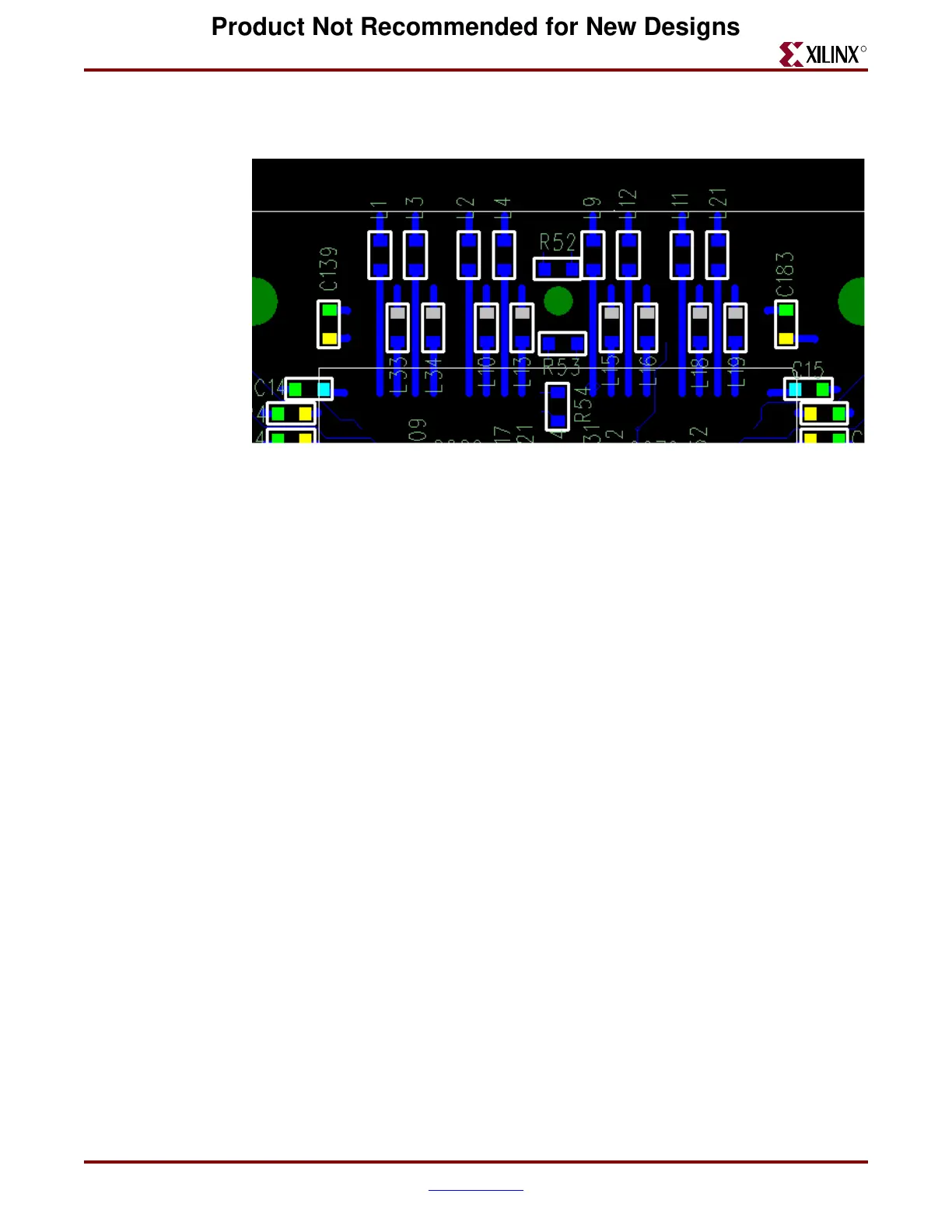
AVCCAUXTX, and AV C C AUXRX supplies. The ferrite beads are mounted at the sixteen
“L[n]” locations.
The device in Figure 3-10 and Figure 3-11 is an FG456 package, which also has eight
transceivers total – four on the top edge, and four on the bottom edge. This device does not
have capacitors inside the package, so it is necessary to have both capacitors and ferrite
beads mounted on the PCB. Figure 3-10 shows the top PCB layer, with lands for the
capacitors and ferrite beads of the VTTX and VTRX supplies. Figure 3-11 shows the bottom
PCB layer, with lands for the capacitors and ferrite beads of the AVCCAUXTX and
AVCCAUXRX supplies. The ferrite beads are mounted at the eight “L[n]” locations; the
capacitors are mounted at the eight “C[n]” locations.
Figure 3-9: Example Power Filtering PCB Layout for Four MGTs, in Device with
Internal Capacitors, Bottom Layer
Product Not Recommended for New Designs