VCU118 Board User Guide 83
UG1224 (v1.0) December 15, 2016
www.xilinx.com
Chapter 3: Board Component Descriptions
Information about the TCA9548 is available on the TI Semiconductor website [Ref 25].
Status and User LEDs
[Figure 2-1, callouts 24]
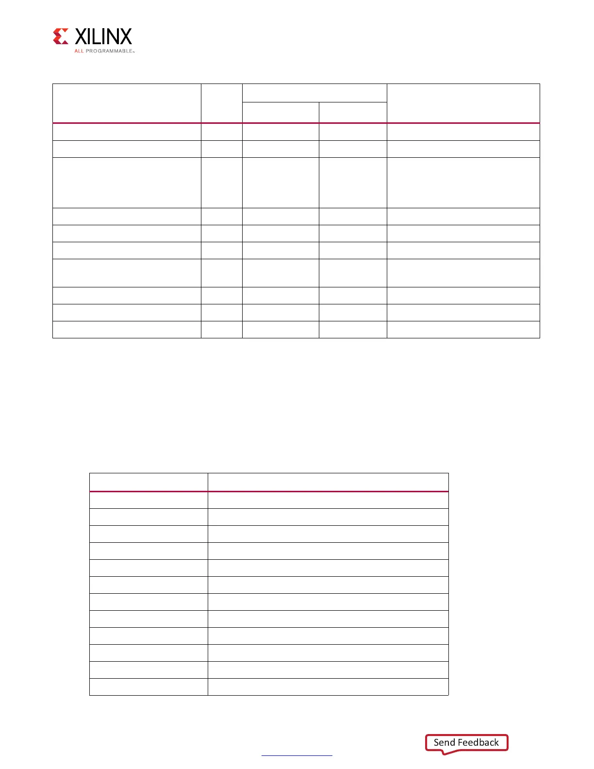
Table 3-28 defines VCU118 board status and user LEDs.
FireFly Connector 7 0b1010000 0x50 J6 UEC5, UCC8
TCA9548 8-Channel bus switch N/A 0b1110101 0x75 U80 TCA9548
PMBus regulators 0
0b0010000-0
b0011000
0x11-0x1B,
0x70-0x73
Various Maxim
Regulators.MAX15301:U4,U6,U9,
U30,U150,U156;
MAX20751EKX: U164,U165,U166
FMCP HSPC (FMC Plus) 1 0bXXXXX00 0x## J22 FMCP HSPC
FMC HPC1 2 0bXXXXX00 0x## J2 FMC HPC
I
2
C EEPROM 3 0b1010000 0x50 U12 M24C08
PMBus INA226AIDGS power
monitor
4
0b0010000-0
b1001000
0x40 -
0x48
U8,U23,U27,U29,U35,U36,U37
SI570_2 clock 5 0b1011101 0x5D U38 SI570
Not used 6 N/A N/A N/A
Not used 7 N/A N/A N/A
Table 3-27: I
2
C Bus Addresses (Cont’d)
I
2
C Devices
I
2
C
Switch
Position
I
2
C Address
Device
Binary Format Hex Format
Table 3-28: VCU118 Board Status and User LEDs
Reference Designator Description
DS1 ENET PHY link
DS2 FPGA INIT
DS3 Combined power good
DS4 SYS_2V2 ON
DS5 VCCINTIO_BRAM On
DS6 GPIO_LED_1
DS7 GPIO_LED_0
DS8 GPIO_LED_2
DS9 GPIO_LED_5
DS10 GPIO_LED_4
DS12 GPIO_LED_5
DS13 GPIO_LED_6