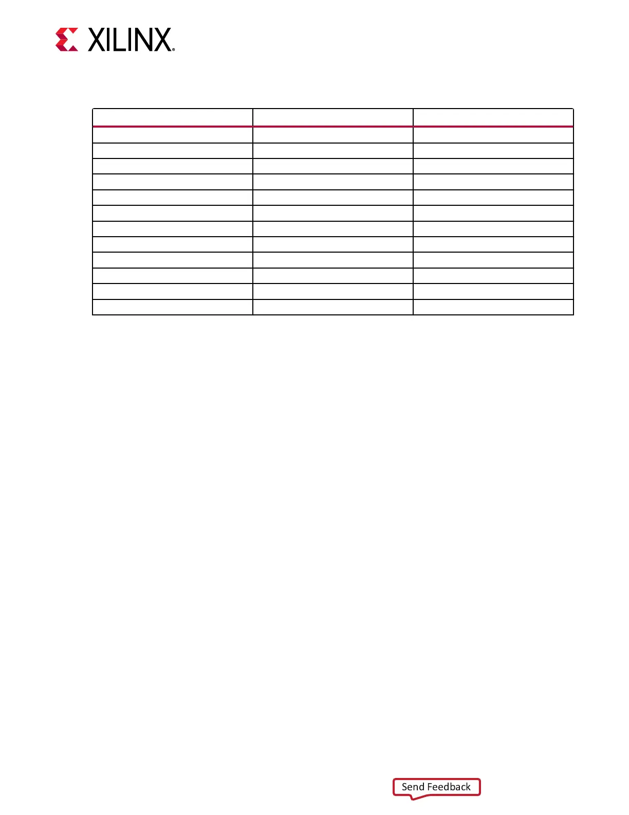
Table 15: IP4856CX25 U23 Adapter Pinout (cont'd)
Aires Adapter Pin Number IP4856CX25 U23 Pin Number IP4856CX25 U23 Pin Name
14 B2 SEL
15 B1 DATA3_H
16 E1 DATA1_H
17 E3 DIR_1_3
18 A1 DATA2_H
19 E5 DATA1_SD
20 D5 DATA0_SD
21 C5 CLK_SD
22 D4 CMD_SD
23 B5 DATA3_SD
24 A5 DATA2_SD
25 C2 ENABLE
For more informaon on the IP4856CX25, see the NXP website.
The detailed RFSoC connecons for the feature described in this secon are documented in the
ZCU208 board XDC le, referenced in Appendix B: Xilinx Design Constraints.
USB0 (MIO 52-63) USB 3.0 Transceiver and USB 2.0
The USB interface on the PS-side serves mulple roles as a host or device controller. The USB
3.0 interface (host mode only) is supported by the RFSoC GTR interface while the USB 2.0 (host
and device modes) capabilies of the SMSC USB3320C controller are shared on a common USB
3.0 micro USB type A connector (J18).
USB 3.0 Transceiver and USB 2.0 ULPI PHY
[Figure 2, callout 6]
The ZCU208 board uses a Standard Microsystems Corporaon USB3320 USB 2.0 ULPI
Transceiver (U6) to support a USB connecon to the host computer. A USB cable is supplied in
the ZCU208 Evaluaon Kit (standard-A connector to host computer, USB 3.0 A connector to
ZCU208 board connector J18). The USB3320 is a high-speed USB 2.0 PHY supporng the UTMI
+ low pin interface (ULPI) interface standard. The ULPI standard denes the interface between
the USB controller IP and the PHY device which drives the physical USB bus. Use of the ULPI
standard reduces the interface pin count between the USB controller IP and the PHY device.
The following gure shows the USB 3.0 interface. USB 3.0 is host mode only.
Chapter 3: Board Component Descriptions
UG1410 (v1.0) July 8, 2020 www.xilinx.com
ZCU208 Board User Guide 38

 Loading...


