The ZCU208 board hosts a quad zSFP/zSFP+ connector (J29) that accept zSFP or zSFP+
modules. The connectors are housed within a single 2x2 zSFP cage assembly. The following
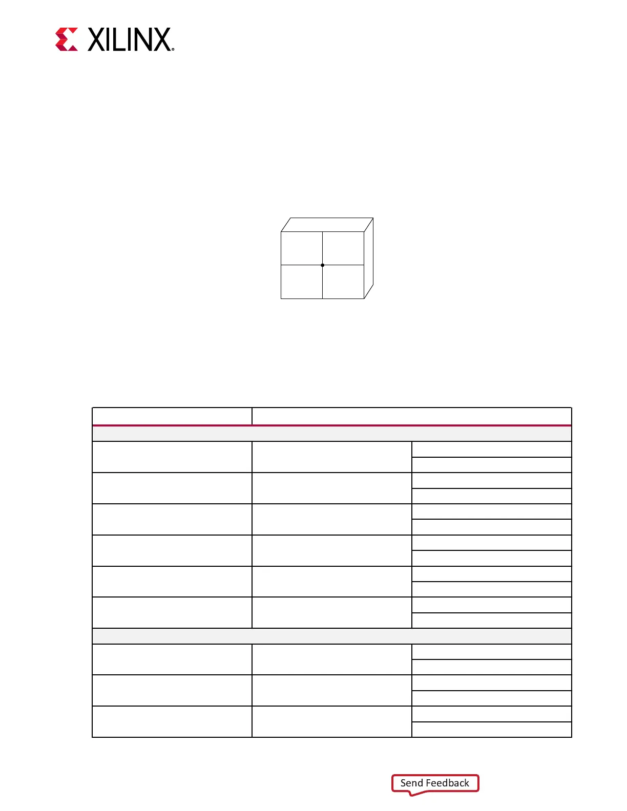
gure shows the zSFP/zSFP+ module locaons within J29.
Figure 16: Quad-zSFP Connector zSFP Locations
Looking at the J29 front opening:
First character: L = Left, R = Right,
Second character: T = Top, L = Lower
LT-
SFP0
LL-
SFP1
RT-
SFP2
RL-
SFP3
X24156-062520
The detailed RFSoC connecons for the feature described in this secon are documented in the
ZCU208 board XDC le, referenced in Appendix B: Xilinx Design Constraints.
The following table lists the zSFP+ module control and status connecons.
Table 19: zSFP Control and Status Board Connections
zSFP Control/ Status Signal Board Connection
SFP0 J29 LT
1, 2
SFP_TX_FAULT Test Point TP11 High = Fault
Low = Normal Operation
SFP_TX_DISABLE Jumper J39
Switch Q6 U1.K16
Off = SFP Disabled
On = SFP Enabled
SFP_MOD_DETECT Test Point J12 High = Module not present
Low = Module Present
SFP_RS0 PU R262 / PD R269 PU R262 = Full RX bandwidth
PD R269 = Reduced RX bandwidth
SFP_RS1 PU R263 / PD R264 PU R263 = Full TX bandwidth
PD R264 = Reduced TX bandwidth
SFP_LOS Test Point TP13 High = Loss of receiver signal
Low = Normal operation
SFP1 J29 LL
1, 2
SFP_TX_FAULT Test Point TP14 High = Fault
Low = Normal Operation
SFP_TX_DISABLE Jumper J44
Switch Q7 U1.K17
Off = SFP Disabled
On = SFP Enabled
SFP_MOD_DETECT Test Point TP15 High = Module not present
Low = Module Present
Chapter 3: Board Component Descriptions
UG1410 (v1.0) July 8, 2020 www.xilinx.com
ZCU208 Board User Guide 47

 Loading...


