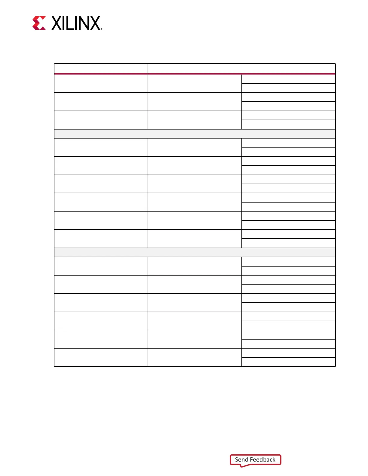
Table 19: zSFP Control and Status Board Connections (cont'd)
zSFP Control/ Status Signal Board Connection
SFP_RS0 PU R270 / PD R273 PU R270 = Full RX bandwidth
PD R273 = Reduced RX bandwidth
SFP_RS1 PU R271 / PD R274 PU R271 = Full TX bandwidth
PD R274 = Reduced TX bandwidth
SFP_LOS Test Point TP16 High = Loss of receiver signal
Low = Normal operation
SFP2 J29 RT
1, 2
SFP_TX_FAULT Test Point TP5 High = Fault
Low = Normal Operation
SFP_TX_DISABLE Jumper J32
Switch Q4 U1.K14
Off = SFP Disabled
On = SFP Enabled
SFP_MOD_DETECT Test Point TP6 High = Module not present
Low = Module Present
SFP_RS0 PU R279 / PD R281 PU R279 = Full RX bandwidth
PD R281 = Reduced RX bandwidth
SFP_RS1 PU R280 / PD R282 PU R280 = Full TX bandwidth
PD R282 = Reduced TX bandwidth
SFP_LOS Test Point TP7 High = Loss of receiver signal
Low = Normal operation
SFP3 J29 RL
1, 2
SFP_TX_FAULT Test Point TP8 High = Fault
Low = Normal Operation
SFP_TX_DISABLE Jumper J35
Switch Q5 U1.K15
Off = SFP Disabled
On = SFP Enabled
SFP_MOD_DETECT Test Point TP9 High = Module not present
Low = Module Present
SFP_RS0 PU R284 / PD R290 PU R284 = Full RX bandwidth
PD R290 = Reduced RX bandwidth
SFP_RS1 PU R285 / PD R291 PU R285 = Full TX bandwidth
PD R291 = Reduced TX bandwidth
SFP_LOS Test Point TP10 High = Loss of receiver signal
Low = Normal operation
Notes:
1. The RS0/RS1 PU/PD resistors are not populated. There are pull-down resistors built into the zSFP modules that select
the lower bandwidth mode of the module.
2. BW selection is also available through I2C control.
For addional informaon about the zSFP module, see SFF-8402 and SFF-8432 on the SNIA
Technology Aliates website.
Chapter 3: Board Component Descriptions
UG1410 (v1.0) July 8, 2020 www.xilinx.com
ZCU208 Board User Guide 48

 Loading...


