25
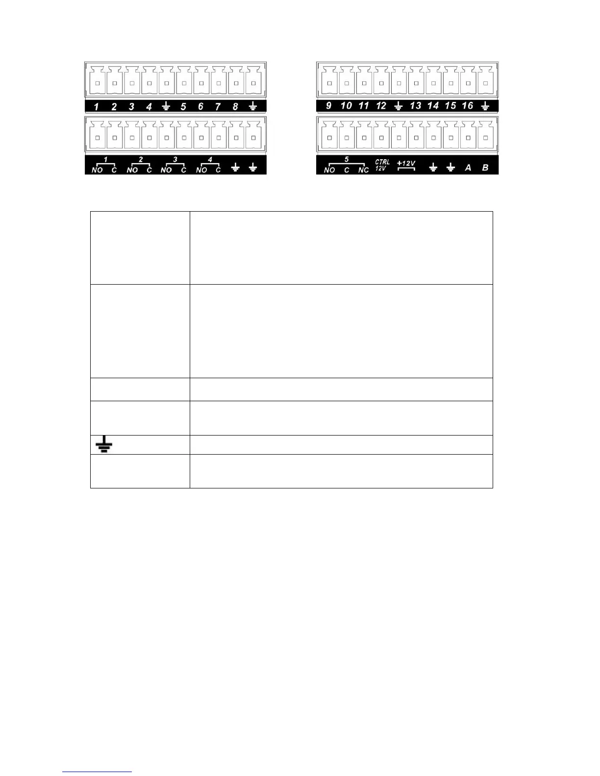
Figure 3-6
In the first line, from
the left to the right,:
1,2,3,4,5,
6,7,8,9,10,
11,12,13,14,
15,16
ALARM 1 to ALARM 16. The alarm becomes active in low voltage.
In the second line,
from the left to the
right:
NO1 C1,
NO2 C2,
NO3 C3,
NO4 C4,
NO5 C5 NC5
The first four are four groups of normal open activation output
(on/off button)
NO5 C5 NC5 is a group of NO/NC activation output (on/off button)
CTRL 12V Control power output. You need to close the device power to cancel
the alarm.
+12V It is external power input. Need the peripheral equipment to provide
+12V power (below 1A).
Earth cable.
485 A/B 485 communication port. They are used to control devices such as
PTZ. Please parallel connect 120TΩ between A/B cables if there are
too many PTZ decoders.T
3.8.2 Alarm Input Port
Please refer to the following sheet for more information.
z 4/8/16-ch grounding alarm inputs. (Normal open or Normal close type)
z Please parallel connect COM end and GND end of the alarm detector (Provide external power to
the alarm detector).
z Use the controllable +12V power to reset the smoke sensor remotely.
z Please parallel connect the Ground of the DVR and the ground of the alarm detector.
z Please connect the NC port of the alarm sensor to the DVR alarm input(ALARM)
z Use the same ground with that of DVR if you use external power to the alarm device.
 Loading...