3.5 Internal frequency converter controller functions
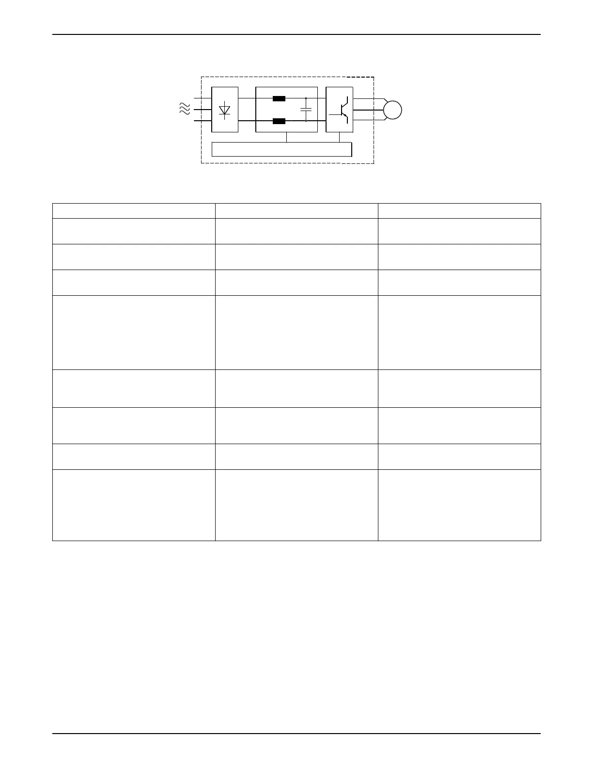
Figure 19: Frequency converter block diagram
Area Title Functions
1 Mains input Three-phase AC mains power supply to the
frequency converter
2 Rectifier The rectifier bridge converts the AC input to DC
current to supply inverter power.
3 DC bus Intermediate DC-bus circuit handles the DC
current
4 DC reactors • Filter the intermediate DC circuit voltage
• Proveide line transient protection
• Reduce RMS current
• Raise the power factor reflected back to
the line
• Reduce harmonics on the AC input
5 Capacitor bank • Stores the DC power
• Provides ride-through protection for short
power losses
6 Inverter Converts the DC into a controlled PWM AC
waveform for a controlled variable output to
the motor.
7 Output to motor Regulated three-phase output power to the
motor
8 Control circuitry • Input power, internal processing, output,
and motor current are monitored to
provide efficient operation and control.
• User interface and external commands are
monitored and performed.
• Status output and control can be provided.
3 Product Description
24 Aquavar
®
Intelligent Pump Controller - 150 HP to 600 HP INSTRUCTION MANUAL