3.4 Description
10
11
1
15
14
12
13
(IP 21/54
NEMA 1/12)
13 (IP 20/Chassis)
8
9
16
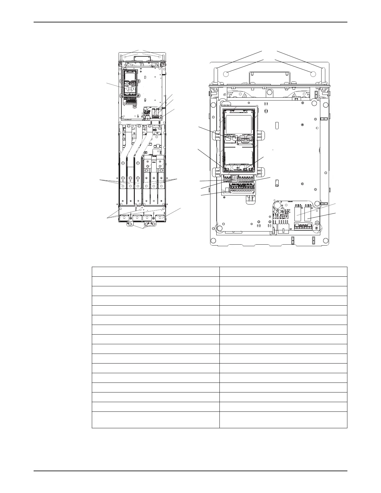
Figure 17: D1 Interior components
Figure 18: Close-up view: LCP and control functions
1 LCP
2 RS-485 serial bus connector
3 Digital I/O and 24 V power supply
4 Analog I/O connector
5 USB connector
6 Serial bus terminal switch
7 Analog switches (A53), (A54)
8 Relay 1 (01, 02, 03)
9 Re;ay 2 (04, 05, 06)
10 Lifting ring
11 Mounting slot
12 Cable clamp (PE)
13 Ground
14 Motor output terminals 96 (U), 97 (V), 98 (W)
15 Line power input terminals 91 (L1), 92 (L2), 93 (L3)
16 TB5 (IP21/54 only). Terminal block for anti-condensation
heater.
For location of TB6 (terminal block for contactor), see Terminal Locations: D5h-D8h.
3 Product Description
Aquavar
®
Intelligent Pump Controller - 150 HP to 600 HP INSTRUCTION MANUAL 23