E
F
B
C
D
A
0 (0.0)
0 (0.0)
0 (0.0)
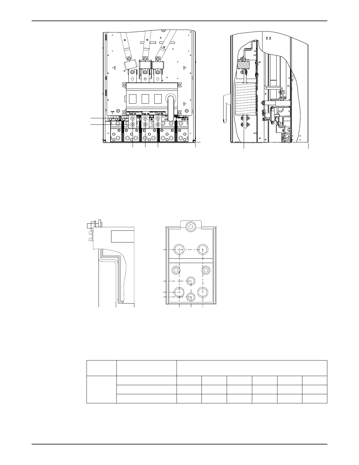
Figure 35: IP00 Enclosure Power Connections Positions of Disconnect Switch
The power cables are heavy and difficult to bend. Consider the optimum position of the
frequency converter for ensuring easy installation of the cables.
Each terminal allows use of up to 4 cables with cable lugs or use of standard box lug.
Ground is connected to relevant termination point in the frequency converter.
If lugs are wider than 39 mm, install supplied barriers on the mains input side of the
disconnect.
104 (4.1)
35 (1.4)
10 (0.4)
0 (0.0)
0 (0.0)
40 (1.6)
78 (3.1)
0 (0.0)
26 (1.0)
26 (1.0)
Figure 36: Terminal in Detail
Power connections can be made to positions A or B.
Table 5: Dimensions for Disconnect Terminal
Enclosure
size
Unit type Dimensions (mm) / (in)
E2
IP00/Chassis A B C D E F
450–600 HP (575 V) 396 (15.6) 268 (10.6) 333 (13.1) 398 (15.7) 221 (8.7) N/A
500–600 HP (400 V) 408 (16.1) 239 (9.4) 319 (12.5) 399 (15.7) 113 (4.4) 153 (6.0)
4.1.8 Gland/Conduit entry IP21 (NEMA 1) and IP54 (NEMA12)
Cables are connected through the gland plate from the bottom. Remove the plate and
plan where to place the entry for the glands or conduits.
4 Mechanical Installation
34 Aquavar
®
Intelligent Pump Controller - 150 HP to 600 HP INSTRUCTION MANUAL