B
B
A
A
412
(16.2)
B-B
A-A
R
S
T
U
V
W
1
2
3
4
0
(0)
119
(4.7)
276
(10.9)
0
(0)
372
(14.7)
545
(21.4)
515
(20.3)
395
(15.6)
0
(0)
49
(1.9)
95
(3.7)
66
(2.6)
151
(5.9)
131
(5.1)
195.5
(8)
292
(11.5)
238
(9.4)
0
(0)
346
(13.6)
368
(14.5)
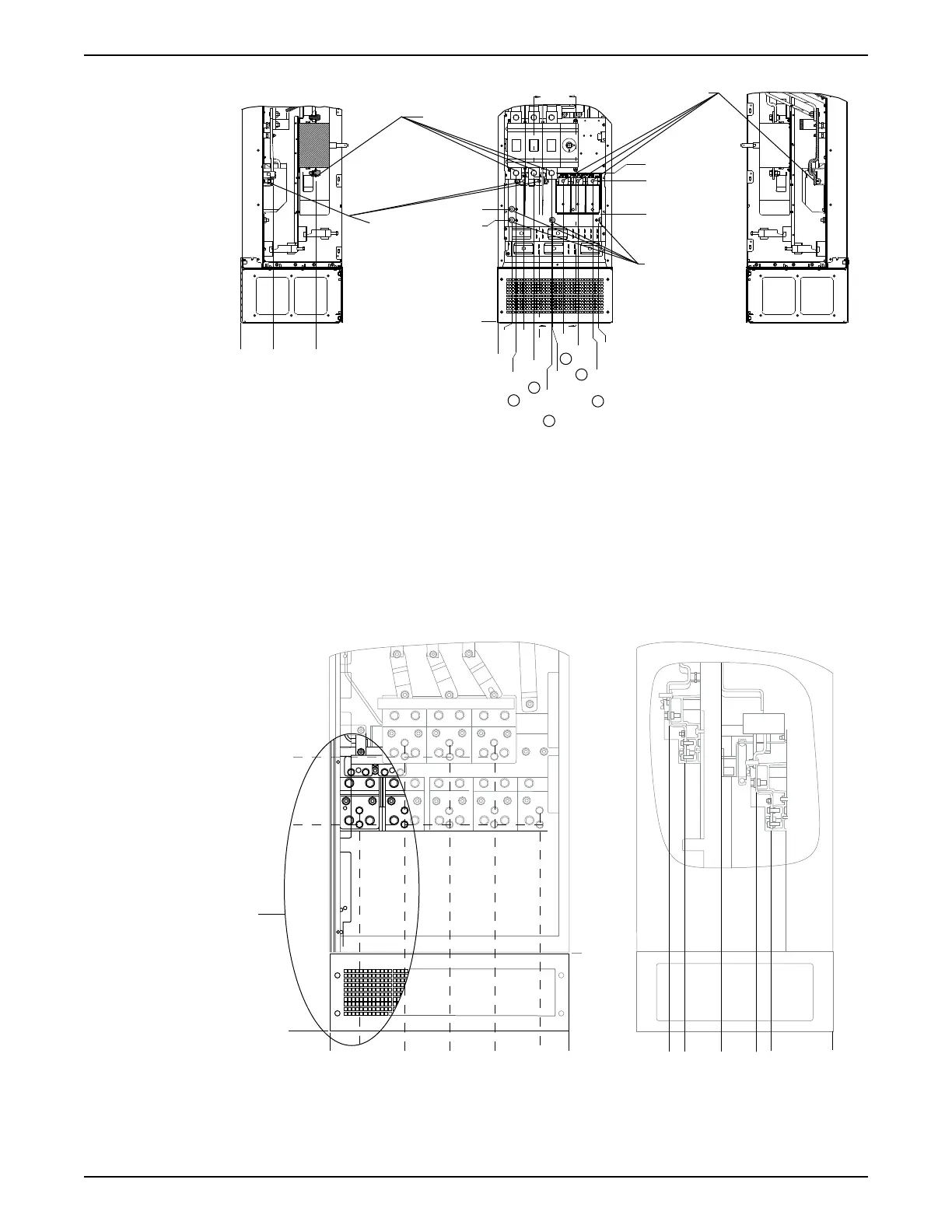
Figure 29: Terminal locations — D7h with disconnect option
1. Mains terminals
2. Brake terminals
3. Motor terminals
4. Earth/Ground terminals
Terminal locations — E enclosures
Consider the following terminal positions when designing the cable access.
Terminal locations — E1
0 (0.0)
0 (0.0)
600 (23.6)
525 (20.7)
412 (16.2)
300 (11.8)
188 (7.4)
75 (3.0)
B
492 (19.4)
323 (12.7)
195 (7.7)
0 (0.0)
155 (6.1)
193 (7.6)
280 (11.0)
371 (14.6)
409 (16.1)
Figure 30: IP21 (NEMA Type 1) and IP54 (NEMA Type 12) Enclosure Power Connection Positions
4 Mechanical Installation
30 Aquavar
®
Intelligent Pump Controller - 150 HP to 600 HP INSTRUCTION MANUAL