*
91 (L1)
92 (L2)
93 (L3)
PE
88 (-)
89 (+)
50 (+10 V OUT)
53 (A IN)
54 (A IN)
55 (COM A IN)
0/4–20 mA
12 (+24 V OUT)
13 (+24 V OUT)
18 (D IN)
20 (COM D IN)
15 mA 200 mA
(U) 96
(V) 97
(W) 98
(PE) 99
(COM A OUT) 39
(A OUT) 42
0/4–20 mA
03
0–10 V DC
+10 V DC
0/4–20 mA
240 V AC, 2 A
24 V DC
02
01
05
04
06
240 V AC, 2 A
24 V (NPN)
0 V (PNP)
0 V (PNP)
24 V (NPN)
19 (D IN)
24 V (NPN)
0 V (PNP)
27
24 V
0 V
(D IN/OUT)
0 V (PNP)
24 V (NPN)
(D IN/OUT)
0 V
24 V
29
24 V (NPN)
0 V (PNP)
0 V (PNP)
24 V (NPN)
33 (D IN)
32 (D IN)
ON
2
1
S202
ON=0–20 mA
OFF=0–10 V
95
400 V AC, 2 A
P 5-00
(R+) 82
(R-) 81
37 (D IN)
+ - + -
130BA544.13
(P RS485) 68
(N RS485) 69
(COM RS485) 61
0V
5 V
S801
RS485
RS485
21
ON
S801
3-phase
power
input
DC bus
Switch mode
power supply
Motor
Analog output
Interface
Relay1
Relay2
ON=Terminated
OFF=Open
Brake
resistor
(NPN) = Sink
(PNP) = Source
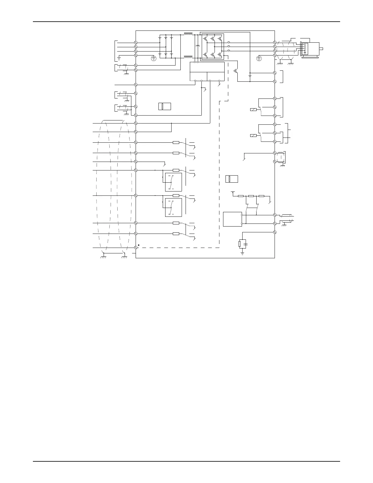
Figure 47: Basic electrical connection
Terminal 37 is the input to be used for Safe Stop. For instructions on safe stop installation,
refer to the section Safe Stop Installation in the adjustable frequency drive Design Guide.
See also section Safe Stop and Safe Stop Installation.
In rare cases, very long cables and analog signals may, depending on installation, result in
50/60 Hz ground loops due to noise from power line supply cables.
If this occurs, it may be necessary to break the shield or insert a 100 nF capacitor between
shield and chassis.
Digital and analog inputs and outputs
The digital and analog inputs and outputs must be connected to the adjustable frequency
drive common inputs (terminal 20, 55, 39) to avoid ground currents from both groups to
affect other groups. For example, switching on the digital input may disturb the analog
input signal.
5 Electrical Installation
42 Aquavar
®
Intelligent Pump Controller - 150 HP to 600 HP INSTRUCTION MANUAL