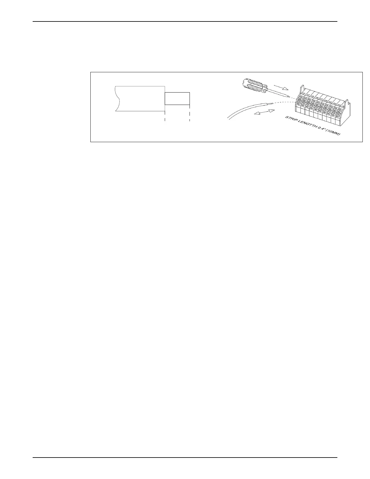
c. Insert the cable in the adjacent circular hole.
d. Remove the screwdriver. The wire is now mounted to the terminal.
2. To remove the wire from the terminal:
a. Insert a screwdriver (2.5–3.5 mm) in the rectangular hole and push it down.
b. Pull out the cable.
Figure 72: Connecting and disconnecting control wiring
Analog input configuration
There are two analog input switches, A53 is fixed to Current (4-20mA) only; whereas, the
A54 input switch can be selected as Voltage (0-10V) or Current (4-20mA).
• Switch A53 is fixed to current type and not configurable.
• Switch A54 is used to configure analog input 54.
If the analog input 54 is used, the analog input configuration switch A54 must be set
properly.
• Remove power from the controller before changing the analog input configuration
switches.
• Remove the local control panel.
• To configure the analog input 54 as a voltage input, set the configuration switch A54 to
U (set to the left position).
• Set the configuration switch A54 to I (set to the right position) to enable the input as a
current input.
Transducer voltage or current type of switch A54 can be verified at parameter [16-63]
Terminal 54 Switch Setting. NOTE: [16-61] Terminal 53 Switch Setting always displays
current type.
5 Electrical Installation
Aquavar
®
Intelligent Pump Controller - 150 HP to 600 HP INSTRUCTION MANUAL 63