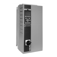
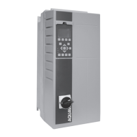
1. Controller Status
2. Motor HP (Parameter [0-20])
3. Motor Frequency (Parameter [0-21])
4. Motor Current (Parameter [0-22])
5. Feedback/Actual Pressure or process variable (Parameter [0-23])
6. Setpoint (Parameter [0-24])
7. Menu keys
8. Navigation keys
9. Operation keys
10.Status lights
The parameters shown are the factory default settings. To display other values, modify
parameters [0–20], [0–21], [0–22], [0–23], or [0–24].
Controller status
The controller status line shows operational information about the controller.
The first word in the status line shows the Operation Mode. The table below defines the
Operation Mode status.
Off The controller does not react to any control signal until
[Auto On] is pressed.
Auto On The controller is controlled from the control terminal
and/or the serial communication.
Hand On The controller can be controlled by the navigation keys on
the LCP. Stop commands, reset, reversing, DC brake, and
other signals applied to the control terminals can
override local control.
The second word in the status line shows the Reference Site.
Remote The speed reference is given from external signals, serial
communication, or internal preset references.
Local The controller converter uses [Hand On] control or
reference values from the LCP.
The third word in the status line shows the Operation Status.
AC Brake AC Brake was selected in [2–10] Brake Function. The AC
brake over-magnetizes the motor to achieve a controlled
slow down.
AMA finish OK Automatic motor adaptation (AMA) was carried out
successfully.
AMA ready AMA is ready to start. Press [Hand On] to start.
AMA running AMA process is in progress.
Braking The brake chopper is in operation. Generative energy is
absorbed by the brake resistor.
Braking max. The brake chopper is in operation. The power limit for the
brake resistor defined in [2–12] Brake Power Limit (kW)
has been reached.
Coast • Coast inverse was selected as a function for a digital
input (parameter group [5–1]* Digital Inputs). The
corresponding terminal is not connected.
• Coast activated by serial communication.
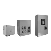
5 Electrical Installation
76 Aquavar
®
Intelligent Pump Controller - 150 HP to 600 HP INSTRUCTION MANUAL