en – Translation of the Original Instructions
e-SV series – Additional Installation, Operation and Maintenance Instructions 21
4.3 Mechanical installation
Install the unit on a concrete or metal foundation base sufficiently strong to ensure permanent
and rigid support.
4.3.1 Installation area
1. Follow the provisions in Operating environment on page 40.
2. Place the unit in a raised position in relation to the floor.
3. Make sure that any leaks will not cause flooding to the installation area or submerge the
unit.
Air clearance between a wall and the motor fan grille
• To ensure suitable ventilation: ≥ 100 mm (4 in)
• To permit inspection and removal of the motor: ≥ 300 mm (12 in)
• If the space available is any less, refer to the technical catalogue.
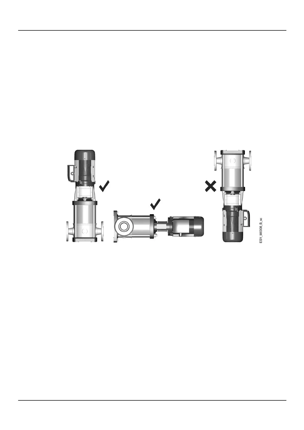
4.3.2 Permitted positions
4.3.3 Installation on concrete foundation
Requirements
• The concrete must have a compression resistance of C12/15 and meet the requirements of
exposure class XC1 according to EN 206-1
• Sizes must be appropriate for the sizes of the unit support plate, see Fastening of the unit
on page 21
• The foundation weight must be ≥ 1.5 times the unit weight (≥ 5 times the weight of the unit
if a quieter operation is required)
• The surface should be as flat and level as possible.
4.3.4 Fastening of the unit
1. If present, remove the plugs covering the suction and discharge ports.
2. Place the unit on the foundation.
3. Using a spirit level, make sure that the unit is level.
4. Align the suction and discharge ports to their piping.
5. Secure the unit with 4 bolts with resistance class 8.8 or higher; see the table.
Also see Reducing vibrations and Hydraulic connection on page 22.

 Loading...