en – Translation of the Original Instructions
e-SV series – Additional Installation, Operation and Maintenance Instructions 23
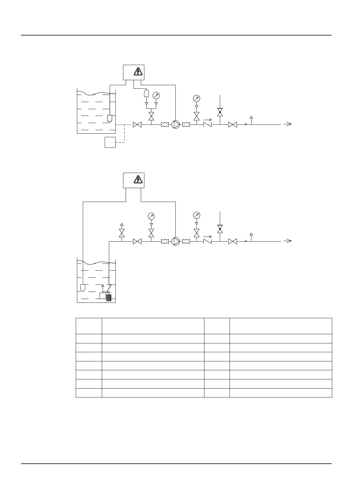
4.4.1 Guidelines for the hydraulic system
Refer to the representative hydraulic diagrams; see the figures below.
Figure 1: Positive suction head installation
Figure 2: Suction lift installation
Electrode probes or float
Overpressure safety on-off valve
Foot check valve with filter
1. Do not install the unit at the lowest point of the system, to avoid the accumulation of
sediments.
2. Install an automatic relief valve at the highest point of the system to eliminate air bubbles.
3. Remove any welding residues, deposits and impurities in the pipes that could damage the
unit; install a filter if necessary.
4. Support the pipes independently to prevent them from weighing on the unit.
EHM_M0016_A_sc
11
5
5
6
8
74 2 2 4
4
4
9
3
Q
1
12
EHM_M0017_A_sc
7
11
5
4
4 2 2
5
4
8
10
3
Q
4
9
1
13