en – Translation of the Original Instructions
e-SV series – Additional Installation, Operation and Maintenance Instructions 13
Serial number + manufacturing date
(
∗
)
Data present only on the pump unit plate
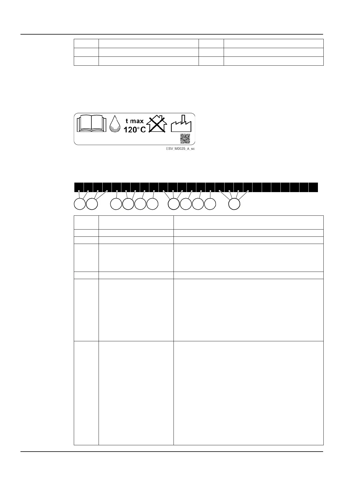
Additional liquid temperature plate
It is applied on the units where the maximum working temperature of the liquid exceeds the
limit of 90°C (194°F), foreseen by the standard EN 60335-2-41, with Un (V) ≤ 480 V (3~) or ≤
250 V (1~).
3.3 Identification code
Modes 1, 3, 5, 10, 15, 22SV
H = with Hydrovar®
X = other drivers
F = AISI 304, round flanges (PN 25)
T = AISI 304, oval flanges (PN 16)
R = AISI 304, overlapping ports, round flanges (PN 25)
N = AISI 316, round flanges (PN 25)
V = AISI 316, Victaulic® couplings (PN 25)
P = AISI 316, Victaulic® couplings (PN 40)
C = AISI 316, DIN 32676 Clamp couplings (PN 25)
K = AISI 316, DIN 11851 thread couplings (PN 25)
L = Low NPSH, round flanges, PN 25 (versions F, N, R)
H = high temperature 150°C, round flanges, PN 25 (versions F, N)
B = high temperature 180°C, round flanges, PN 25 (version N)
E = passivated and electropolished (versions N, V, C, K, P)
W = high temperature 150° and low NPSH (versions F, N)
Y = high temperature 180° and low NPSH (version N)
U = passivated, electropolished and low NPSH (versions N, V, C, K, P)
I = high temperature 150°, passivated and electropolished (version N)
S = high temperature 180°, passivated and electropolished (version N)
A = high temperature 150°, passivated, electropolished and low NPSH
(version N)
D = high temperature 180°, passivated, electropolished and low NPSH
(version N)
EHM_M0005_A_sc
2 2
S V 1
0 F
L 1 1 0
T
1
13
1 15
16
18
1
9
110
111
1
2 4
7