en – Original instructions
31
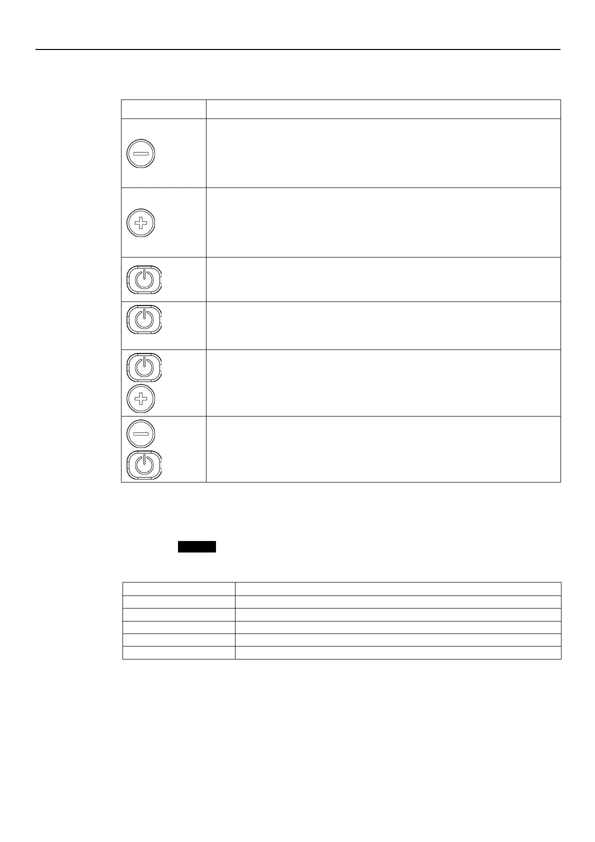
6.2 Description of the buttons
•
Main view (see Par. 6.4.1): decreases the required value for the selected control mode
•
Parameter menu (see Par. 6.4.2): decreases the displayed parameter index
•
Parameter view / editing (see Par. 6.4.2): decreases the value of the displayed parameter
•
Zero pressure auto-calibration (see Par. 6.5, P44): automatic calibration of the pressure
•
Main view (see Par. 6.4.1): increases the required value for the selected control mode
•
Parameter menu (see Par. 6.4.2): increases the displayed parameter index
•
Parameter view / editing (see Par. 6.4.2): increases the value of the displayed parameter
•
Zero pressure auto-calibration (see Par. 6.5, P44): automatic calibration of the pressure
•
Main view (see Par. 6.4.1): START/STOP the pump
•
Parameter menu (see Par. 6.4.2): switches to parameter view / editing
•
Parameter view / editing (see Par. 6.4.2): saves the value of the parameter.
•
Main view (see Par. 6.4.2): switches to parameter selection
•
Parameters Menu: switches to Main Visualization
and
Main view: alternates between Speed and Head units of measure (see Par. 6.4.1).
and
Main view: alternates between Speed and Head units of measure (see Par. 6.4.1).
6.3 LEDs description
6.3.1 POWER (power supply)
When ON (POWER) the pump is powered and the electronic devices are operational.
6.3.2 STATUS
Flashing green and orange
Non-locking alarm with the pump unit in operation
Non-locking alarm with the pump unit stopped
Locking error, the pump unit cannot be started
6.3.3 SPEED (speed bar)
It consists of 10 LEDs, each representing, in percentage steps between 10 and 100%, the speed
range between parameter P27 (minimum speed) and parameter P26 (maximum speed).