en – Original instructions
35
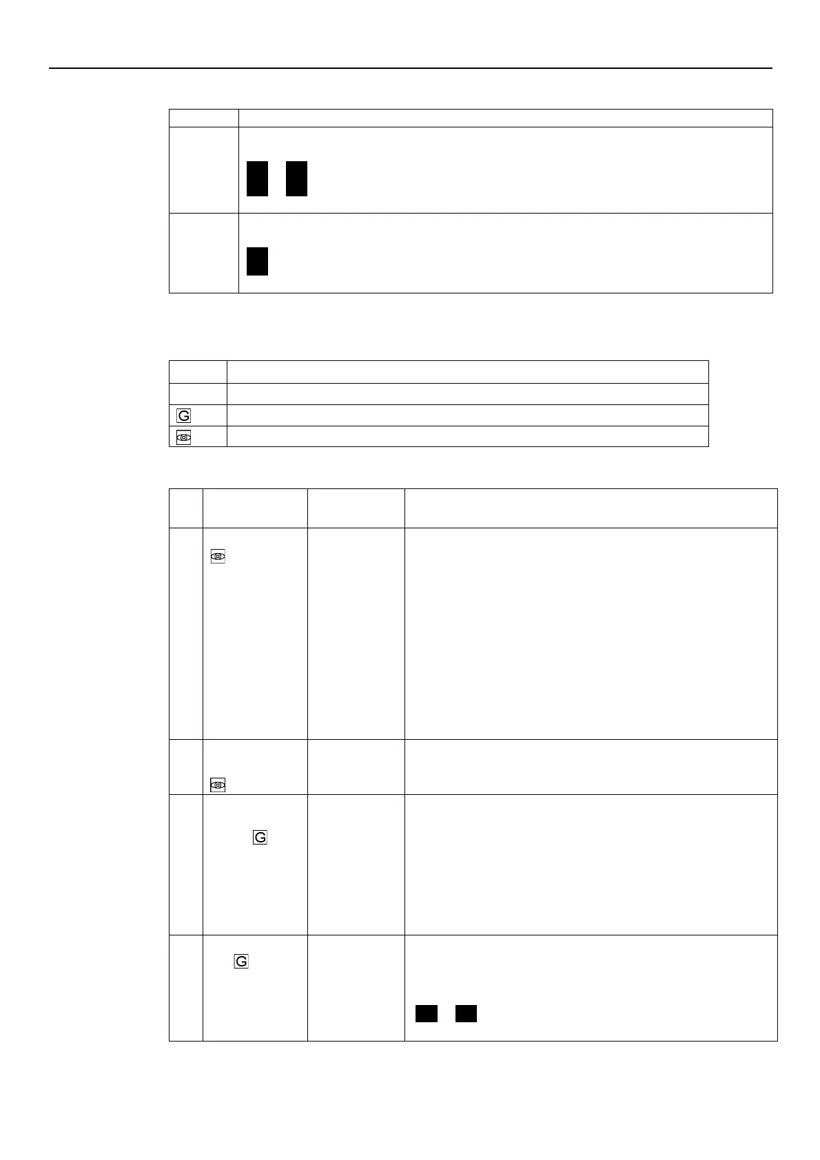
6.4.3 Alarms and errors visualization
In case of alarm, the corresponding code appears on the display in alternation to the Main View.
For example:
A01
→
3.56
(ex. BAR)
A02
→
285
(ex. 10xRPM)
In case of error, the corresponding identification code appears on the display.
For example:
E01
E02
6.5 Software parameters
Parameters are marked differently in the manual depending on their type:
Global parameter, shared by all pumps in the same multi-pump system
6.5.1 Status Parameters
rpmx10
This parameter shows the SOURCE and the VALUE of the active
required value.
Visualization cycles between SOURCE and VALUE occur every 3
seconds.
SOURCES:
•
SP (SP): internal required value Setpoint related to the control
mode selected.
•
VL (UL): external required value speed Setpoint related to 0-10V
input.
VALUE can represent a Speed or a Head, depending on the selected
control mode:
in case of Head, the unit of measure is defined by parameter P41.
Required Value
Active required value calculated based on parameters P58 and P59.
This parameter is effective only in control modes MSE or MSY.
For further information on the calculation of P02, see Par. 6.6.3.
Restart Value
[0÷100]
It defines the start value after the stop of the pump, as a percentage of
the P01 value. If the required value is met and there is no further
consumption, then the pump stops. The pump starts again when the
pressure drops below P03.
P03 is valid when:
•
Different from 100% (100%=off)
•
The control mode is HCS, MSE or MSY.
ON]
If P04 = ON, then the pump starts automatically following a power
supply disconnection.
If the pump is switched on after setting P04 = OFF (see Par. 6.5.1), it is
stopped so that the motor is not in operation, and STP flashes
(
STP
→
STP
).