en – Original instructions
33
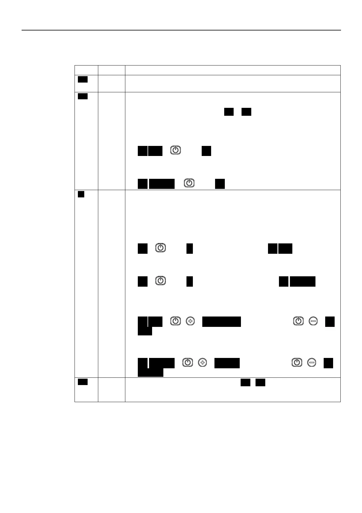
6.4 Display
6.4.1 Main visualization
Contacts 11 and 12 (single-phase version) or 13 and 14 (three-phase version) are not short-
circuited. Note: It has lower display priority than STOP mode.
If the pump is switched on after setting P04 = OFF (see Par. 6.5.1), it is stopped so that the
motor is not in operation, and STP flashes (
STP
→
STP
).
To manually stop the pump:
•
Example A.
HCS, MES, MSY control modes with initial required value (head) of 4.20 bar and minimum
value 0.5 bar:
4.20
BAR
→
press
→
STP
once.
•
Example B.
ACT control mode with initial required value (speed) of 200 10xRPM and minimum value
80 10xRPM:
200
→
→
STP
Pump on; the motor starts following the selected control mode.
It appears for a few seconds when contacts 11 and 12 (single-phase version) or 13 and 14
(three-phase version) are short circuited and the pump is not in STOP mode.
To manually set the pump to ON mode:
•
Example A.
HCS, MES, MSY control modes that reach a required value (head) of 4.20 bar, starting
with a minimum value of 0.5 bar after manual stop:
STP
→
press
→
ON
→
once after a few seconds…
→
4.20
BAR
.
•
Example B.
ACT control mode that reaches a requested value (speed) of 200 10xRPM, starting with a
minimum value of 80 10xRPM after manual stop:
STP
→
press
→
ON
→
once, and after a few seconds…
→
200
10xRPM
.
With the pump in operation, it is possible to display the Actual Head and the Actual Speed:
•
Example A
HCS, MES, MSY control modes with Actual Head 4.20 bar and corresponding Actual
Speed of 352 10xRPM:
4.20
BAR
→
+
→
352
10XRPM
→
after 10 seconds or +
→
4.20
BAR
.
•
Example B
ACT control mode with Actual Speed 200 10xRPM and corresponding Actual Head of 2.37
bar:
200
10xRPM
→
+
→
2.37
BAR
→
after 10 seconds or +
→
200
The analog input is configured as speed set (P40 =
ISP
USP
), the read value is in the Stand-
by zone and P34 = STP (see paragraph 6.6.1)
Note: It has lower display priority than STOP mode