en – Original instructions
42
6.6 Technical references
6.6.1
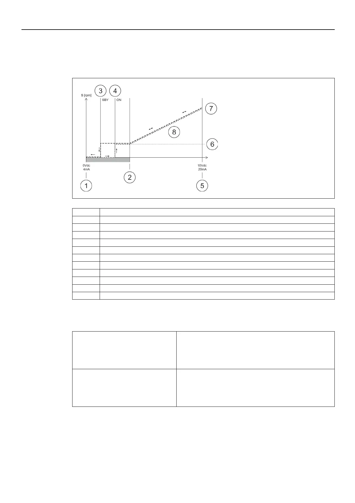
Example: ACT control mode with analog input
The diagram of the ACT control mode is shown in the figure.
ZERO point (0Vdc - 4mA) = minimum analog signal value
Standby point (SBY) = 1/3 of the hysteresis zone
ON point (ON) = 2/3 of the hysteresis zone
MAX point (10Vdc - 2mA) = maximum analog signal value
Motor minimum speed (Parameter P27)
Motor maximum speed (Parameter P26)
Minimum speed operation zone (Parameter P27)
For further information on the control mode and the ACT regulation parameters, see Par. 6.5.3.
Examples:
Calculation of the adjustment start point
for P40 = ISP (4-20 mA analog signal)
•
P26 = 3600
•
Calculation of the adjustment start point value = (maximum value
- zero point) x (P27/P26) + zero point = (20-4) x (900/3600) + 4 = 8
Calculation of the adjustment start point
for P40 = VSP (0-10 Vdc analog signal)
•
P26 = 3600
•
Calculation of the adjustment start point value =
(maximum value - zero point) x (P27/P26) + zero point = (10-0) x