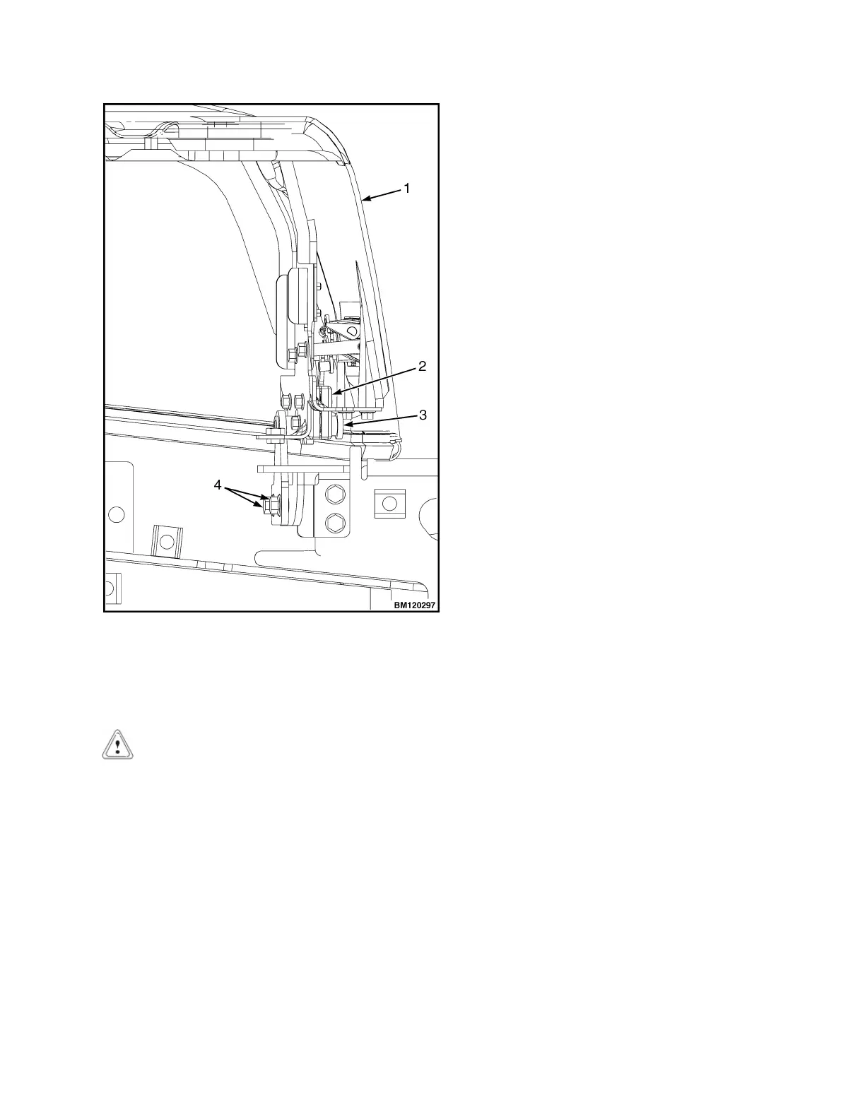
1. HOOD
2. HOOD LATCH
3. CENTER PIN
4. CAPSCREW
Figure 11. Hood Latch Adjustment
CAUTION
When installing the seat to the hood, do not use
an impact wrench to install the capscrews. Dam-
age can be caused to the threads on the screws
and in the holes.
7. Place the seat on the hood and thread the chas-
sis harness through the holes in the hood. See
Figure 8.
8. Align the holes in the seat with the holes in the
hood. See Figure 8. Insert capscrews and nuts.
Tighten capscrews to 18 N•m (159 lbf in).
9. Connect seat harness to chassis harness. Install
cover plate to electrical cover using two cap-
screws and washers. See Figure 7.
10. Using three capscrews, install seal plate. See Fig-
ure 6. Tighten capscrews to
10.8 N•m (95.6 lbf in).
11. Place dash panel on cowl and secure dash panel
to cowl using five Allen Head screws. Tighten Al-
len Head screws to 3.5 N•m (31 lbf in). See Fig-
ure 5.
12. Align notches on kick panel to clips on dash panel
and push kick panel into place on seal plate. See
Figure 6.
13. Raise steering column to highest position and in-
stall upper steering column cover by aligning the
two latches and pushing down until latched. See
Figure 5.
14. Using four capscrews and clip nuts, install the left
and right front side covers and left and right cowl
plates to the frame. See Figure 4.
15. Using two capscrews, install the left and right rear
side covers to the frame. See Figure 4.
16. Install the floor mat and floor plate.
NOTE: Perform Step 17 for lift trucks equipped with
LPG.
17. Swing the LPG tank into position on back of coun-
terweight. See Fuel System PSI 2.4L
0900YRM1757 for procedures.
18. Adjust the steering column and seat positions.
0100 YRM 1766 Hood, Seat, and Side Covers Replacement
11
 Loading...