Legend for Figure 22
A. TOP VIEW B. LEFT VIEW
1. AIR FILTER AND BRACKET ASSEMBLY
2. AIR FILTER HOSE
3. SHROUD
4. RADIATOR CAP
5. COOLANT HOSES
6. NEGATIVE BATTERY CABLE
7. BATTERY AND BATTERY TRAY
8. POSITIVE BATTERY CABLE
9. PDM
10. ENGINE HARNESS CONNECTOR
11. HYDRAULIC RETURN HOSE
12. CHASSIS HARNESS
13. TRANSMISSION MOUNT
14. TRANSMISSION OIL COOLER LINES
15. LPG REGULATOR CONNECTOR
16. HYDRAULIC SUPPLY HOSE
17. EXHAUSTS PIPE TO EXHAUST MANIFOLD
18. LOWER RADIATOR HOSE
19. FAN
20. FAN PULLEY AND FAN SPACER
21. FUEL LINE
WARNING
DO NOT remove the radiator cap from the radiator
when the engine is hot. When the radiator cap is
removed, the pressure is released from the sys-
tem. If the system is hot, the steam and boiling
coolant can cause burns.
5. Let coolant cool to ambient temperature. Place a
drain pan with a capacity greater than the ca-
pacity of the cooling system under radiator. Re-
move radiator cap.
CAUTION
Disposal of lubricants and fluids must meet local
environmental regulations.
6. Open the drain plug or disconnect the bottom ra-
diator hose to drain coolant from radiator and en-
gine. See Figure 22.
7. Remove the hood and seat combination and rear
side covers. See section Hood, Seat, and Side
Covers Replacement for procedures.
8. Disconnect the ground strap from the frame and
remove the power distribution module (PDM) from
the battery tray. See Figure 23.
9. Remove battery and battery tray from lift truck as
described in the steps below:
a. Remove cap, flange nut, and lockwasher from
battery lockdown bar. See Figure 23.
b. Disengage battery lockdown bars and remove
bar from top of battery. See Figure 23.
c. Remove battery from battery tray. See Fig-
ure 23.
d. Remove three capscrews and battery tray from
frame. See Figure 23.
10. Disconnect the remaining coolant hoses from the
radiator and cap them to prevent leakage. See
Figure 22.
11. Remove the radiator fan pulley, shroud, and fan
assembly. See Cooling System - PSI 2.4L En-
gine 0700YRM1767 for the removal procedures.
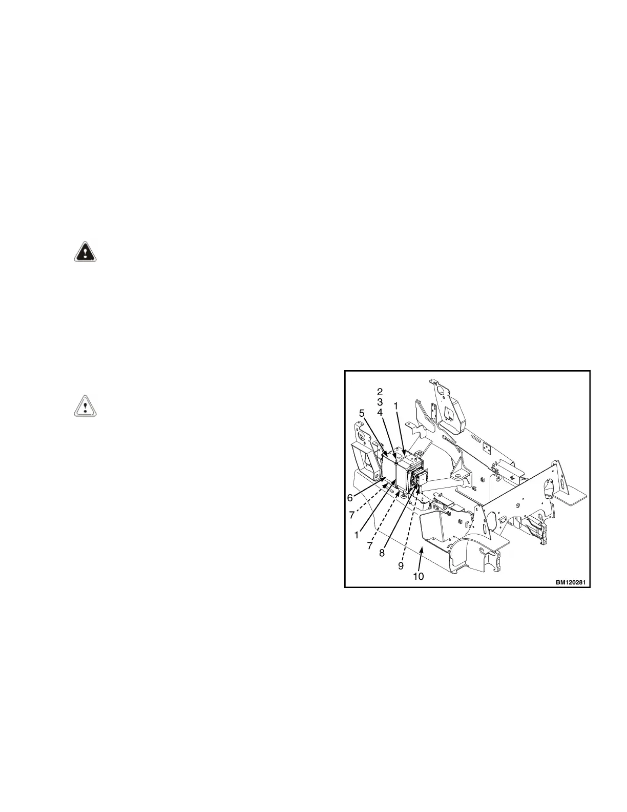
1. BATTERY LOCKDOWN BAR
2. CAP
3. FLANGE NUT
4. LOCKWASHER
5. BATTERY
6. BATTERY TRAY
7. CAPSCREW
8. PDM
9. GROUND STRAP
10. FRAME
Figure 23. Power Distribution Module and Battery
Tray
0100 YRM 1766 Engine Replacement
25