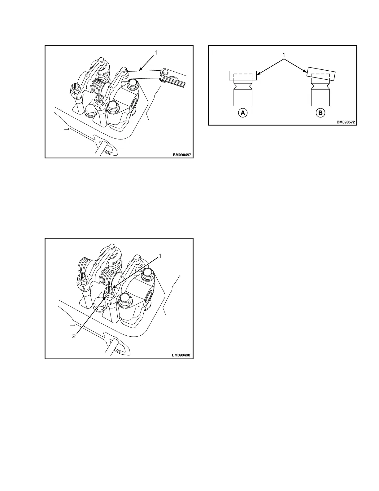
1. FEELER GAUGE
Figure 11. Valve Clearance Measurement
4. If adjustment is needed, loosen the valve adjust-
ing screw lock nut and valve adjusting screw on
the rocker arm (see Figure 12) and check the
valve for any inclination of valve cap, entrance of
dirt, or wear. See Figure 13.
1. VALVE ADJUSTING SCREW
2. VALVE ADJUSTING SCREW LOCK NUT
Figure 12. Valve Clearance Adjustment
A. NORMAL B. ABNORMAL
1. VALVE CAP
Figure 13. Valve Cap Check
NOTE: There is a tendency for the clearance to de-
crease slightly when the lock nut is tightened. It is
suggested that you make the clearance adjustment
slightly on the loose side before tightening the lock
nut.
5. Insert a 0.2 mm (0.008 in.) feeler gauge between
the rocker arm and valve cap and adjust the
clearance so there is a slight drag on the feeler
gauge when sliding it between the rocker arm and
valve cap. Tighten the valve adjusting screw lock
nut and recheck the clearance. The valve clear-
ance should be between 0.15 to 0.25 mm (0.006
to 0.010 in.).
6. Apply clean engine oil to the contact surface be-
tween the adjusting screw and push rod.
7. Turn the crankshaft 180 degrees and make the
measurement and adjustment for the number
three cylinder. Then turn the crankshaft 180 de-
grees and make the measurement and adjust-
ment for the number four cylinder. Then turn the
crankshaft 180 degrees and make the measure-
ment and adjustment for the number 2 cylinder.
8. Install the valve cover. See Valve CoverInstall.
0600 YRM 1205 Cylinder Head Assembly Repair
11
 Loading...