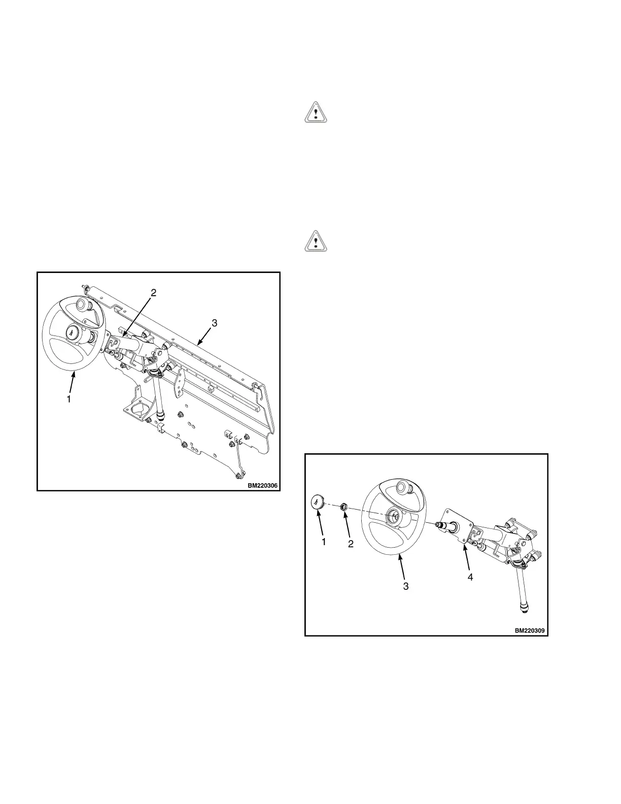
Steering Column
DESCRIPTION
This section describes the repair procedures for the
steering column. The Steering Column Assembly
mounts to the cowl inside the operator compartment
and is the mechanical connection between the steer-
ing wheel and the steering control unit. The steering
column includes the steering wheel, housing, bracket
and lower shaft. For lift trucks with gas and LPG en-
gines, bolts and bushings attach the steering column
to the cowl standoffs. For lift trucks with diesel en-
gines, bolts, bushings and isolators attach the steer-
ing column to the cowl standoffs See Figure 12.
NOTE: DIESEL SHOWN, LPG AND BI-FUEL SIMI-
LAR.
1. STEERING WHEEL
2. STEERING COLUMN
3. COWL
Figure 12. Steering Column and Cowl
STEERING COLUMN REPAIR
Remove
1. Put blocks on each side (front and back) of tires
to prevent lift truck from moving.
CAUTION
Disconnect the negative battery cable on internal
combustion trucks. Disconnect the battery before
removing any covers.
2. Attach a tag on the battery connector or negative
battery cable stating, DO NOT CONNECT BAT-
TERY. Move the steering column to the most
FORWARD position.
CAUTION
If a puller tool is used to remove steering wheel
from steering column, be careful not to damage
horn wires.
NOTE: This procedure is for the removal of all com-
ponents of the steering column assembly. All compo-
nents are not often removed for a repair procedure.
Do only those steps of the procedure necessary to re-
move the required component.
NOTE: Tag wires prior to disconnect
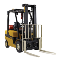
3. Remove the horn button assembly and discon-
nect electrical wires. Remove large hex nut and
steering wheel from steering column. See Fig-
ure 13.
1. HORN BUTTON
2. HEX NUT
3. STEERING WHEEL
4. STEERING COLUMN
Figure 13. Steering Wheel Remove/Install
Steering Column 0100 YRM 1766
12