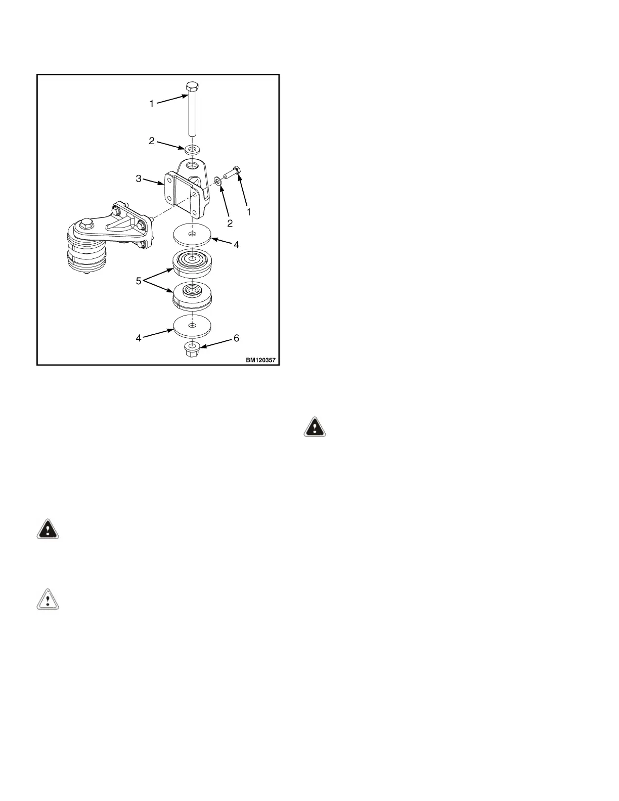
1. CAPSCREW
2. WASHER
3. ENGINE BRACKET
4. SNUBBING WASHER
5. ISOLATOR
6. FLANGE LOCKNUT
Figure 35. Yanmar Engine Mounts
INSTALL
LPG Engine
WARNING
The engine is heavy. Make sure that any lifting de-
vice has enough capacity to lift the engine. The
engine can weigh approximately 194 kg (428 lb).
CAUTION
Keep the engine level when installing the engine
to the transmission so the drive plate is not dam-
aged.
1. Install torque converter in torque converter hous-
ing.
2. Connect lifting device to engine and lift engine
into frame. Install engine adapter to transmission
bolts.
3. Install isolators, bolts, washers, and flange nuts
on engine mounts. See Figure 21, Figure 27, and
Figure 28. Tighten the flange nuts to
150 N•m (110 lbf ft).
4. Use access port on side of engine and install
bolts to hold torque converter to flywheel. Tighten
bolt to 56 N•m (41 lbf ft). See Figure 25.
5. Align torque converter housing holes with flywheel
housing holes and install four capscrews from tor-
que converter housing side. Tighten capscrews to
38 N•m (28 lbf ft). See Figure 26.
6. Install six capscrews in torque converter housing
and flywheel housing from flywheel housing side.
Tighten capscrews to 38 N•m (28 lbf ft). See Fig-
ure 26.
7. Install exhaust pipe to exhaust manifold. See Fuel
System PSI 2.4L 0900YRM1757.
8. Connect engine wiring harness connectors to pro-
portional valve connectors, transducer connec-
tors, solenoid valve connector, temperature sen-
sor connector, and transmission. See Figure 24.
9. Connect chassis wiring harness connectors to en-
gine harness connectors. See Figure 21.
WARNING
All fuels are very flammable and can burn or
cause an explosion. DO NOT use an open flame to
check the fuel level or to check for leaks in the
fuel system.
No smoking.
Breathing fuel vapor may cause nausea, uncon-
sciousness, or death. Long-term exposure to gas-
oline vapors may cause liver or kidney damage
and cancer. Avoid breathing vapor.
10. Remove caps from fuel lines and connect the fuel
lines at the engine.
11. Install the radiator shroud, fan pulley, and fan as-
sembly. See Figure 22. See Cooling System -
PSI 2.4L Engine 0700YRM1767 for the installa-
tion procedures.
12. Connect the coolant hoses and lines to the trans-
mission. Fill cooling system with a mixture speci-
fied in Periodic Maintenance 8000YRM1774.
Engine Replacement 0100 YRM 1766
36