A
1
2
3
4
5
6
7
8
9
10
BCDEFGH I JK
L MN
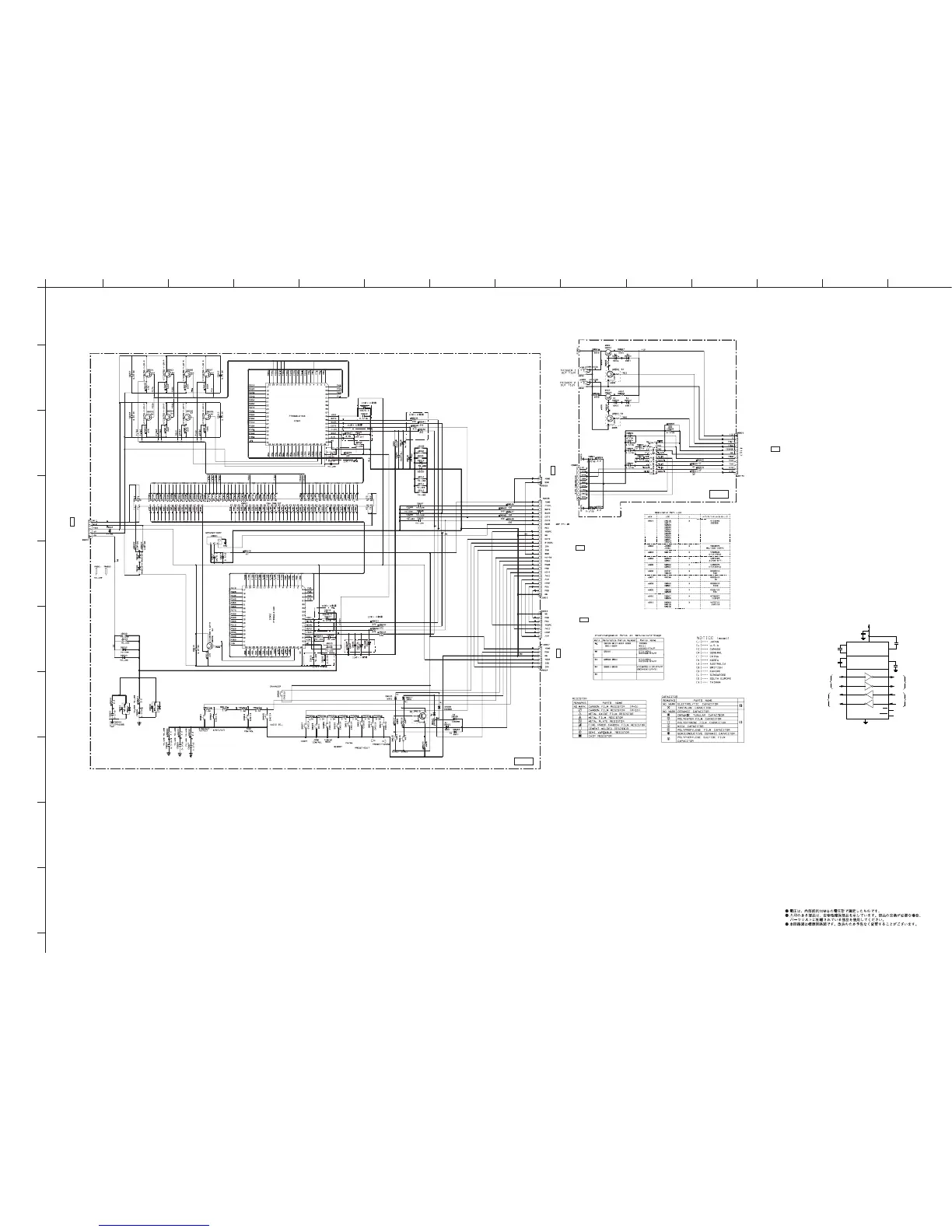
RX-V1700/DSP-AX1700
117
★ All voltages are measured with a 10MΩ/V DC electronic voltmeter.
★ Components having special characteristics are marked s and must be replaced
with parts having specifications equal to those originally installed.
★ Schematic diagram is subject to change without notice.
FL 1/2
5.0
-23.5
5.0
-21.4
-21.9
-25.6
-29.3
-21.3
-23.4
-25.7
-25.7
-27.5
-27.5
-27.5
-27.5
-27.5
-27.5
-27.5
-27.5
-27.5
-27.5
-27.5
-27.3
-29.3
-25.2
-22.9
-25.2
-23.2
-23.5
-25.2
-25.5
-21.2
-21.2
-21.5
-27.5
-27.2
-27.5
-27.4
-23.4
-21.5
-23.5
-23.5
-22.9
-29.5
-27.5
-27.5
-27.4
-21.4
-27.5
-27.5
-27.5
5.0
0
0
4.9
4.9
2.5
0
0
0
0
0
0
0
0
0
0
0
0
-0.1 0
0
0
0
0
2.5
2.6
0
-25.5
-25.5
-23.4
-21.4
-23.4
-25.5
-27.5
-27.3
-27.0
5.0
5.0
-23.0
5.0
-27.0
5.0
-27.3
-23.4
-21.7
-21.7
-27.3-27.5
-25.7
-25.7
-27.5
-27.5
-27.5
-27.5
-27.5
-27.5
-27.5
-27.5
-27.5
-27.5
-27.5
-27.0
-22.9
0
5.1
5.0
-23.5
-23.5
-21.5
-23.4
-27.4
-27.5
-27.2
-27.5
-21.5
-21.2
-21.2
-25.5
-25.2
-23.5
-23.2
-25.2
-22.9
-25.2
-23.4
-21.3
-29.5
-27.5
-27.5
-21.4
-21.4
-27.5
-27.5
-27.5
-25.5
-25.5
-23.4
-21.4
-23.4
-25.5
-19.3
-21.2
-19.3
-23.3
-25.3
-27.3
-25.3
-27.3
-23.3
-25.3
-27.3
-25.3
-27.5
-27.3
-23.4
-21.4
-23.0
-23.5
-20.9
-25.5
-25.4
-21.4
-21.4
-21.4
-27.4
-27.4
-26.7
-27.4
-23.4
-25.4
-21.4
-23.5
-21.4
-22.9
-27.0
-27.1
-27.5
-27.5
-27.5
-27.5
-27.5
-27.5
-27.5
-27.5
-27.5
-27.5
-27.5
-27.5
-27.5
-27.5
-21.7
-21.7
-21.7
-21.7
-21.7
-21.7
-27.5
-27.5
-27.5
-27.5
-27.5
-27.5
-27.5
-27.5
-27.5
-27.5
-27.5
-27.5
-27.5
-27.5
-27.5
-29.3
-27.5
-23.5
-23.5
-20.9
-25.5
-25.4
-21.4
-21.4
-21.4
-27.4
-27.4
-27.5
-27.4
-23.4
-25.4
21.4
-23.5
-21.4
-23.5
-27.5
-25.3
-27.3
-25.3
-23.3
-27.3
-25.3
-27.3 5.0
0.1
0.1
4.9
4.9
2.4
2.4
0
-25.3
-23.3
-19.3
-21.2
-19.3
-27.3
-27.5
-27.1
5.0
-20.9
5.0
-26.7
5.0
-22.9
-23.4
-27.5 -23.5
-27.5 -27.5
-25.5 -27.5
-23.5
11.2
10.5
10.9
0.1
4.9
0
11.2
11.2
10.6
10.9
0.1
4.9
4.2
5.1
10.0
0.1
-9.7
9.5
0
2.6
-2.4
5.1
0
0
-9.2
5.1
4.9
0.1
5.1
0
11.2
FL (1)
FL (6)
FL DRIVER
FL DRIVER
*
INTERNAL 400k W PULL-UP RESISTOR
ON EACH TTL/MOS INPUT
**
INTERNAL 5k W PULL-DOWN RESISTOR
ON EACH RS-232 INPUT
V
CC
+5V TO +10V
VOLTAGE DOUBLER
+5V TO –10V
VOLTAGE INVERTER
C1+
C1–
V+
V–
C2+
C2–
T1
ADM2xx
T2
R1
R2
0.1∝F
0.1∝F
0.1∝F
GND
TTL/CMOS
OUTPUTS
R1
OUT
R2
OUT
T1
OUT
T2
OUT
R1
IN
R2
IN
T1
IN
T2
IN
TTL/CMOS
INPUTS
*
RS-232
OUTPUTS
RS-232
INPUTS
**
0.1∝F
+5V INPUT
0.1∝F
EN
SHDN
(ADM242)
(ADM222, ADM242)
IC951: ADM222ARZ
High speed RS-232 line drivers/receivers
to POWER (1)_CB12
Page 112
B5
to OPERATION (5)_CB809
RS-232C
Page 110
I4
to OPERATION (4)_CB12
Page 110
K3
to OPERATION (1)_CB801
Page 110
K3
to FL (2)_CB970
Page 118
I3
to FUNCTION (1)_CB405
Page 106
C8
 Loading...