RX-V1700/DSP-AX1700
14
RX-V1700/
DSP-AX1700
Fig. 4
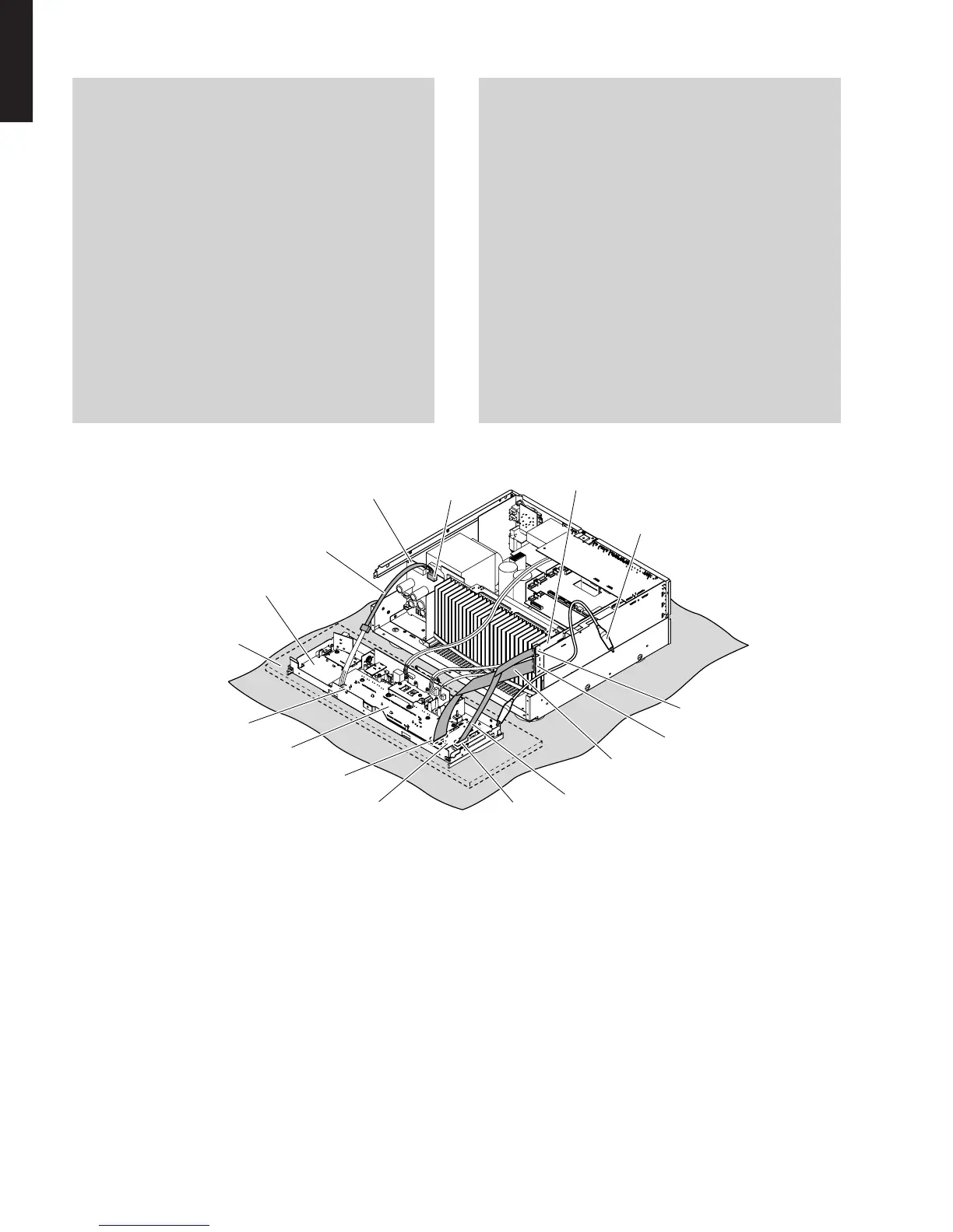
P.C.B.をチェックする場合には:
・ サブシャーシユニットをゴムシートと布の上に置いて
チェックします。(Fig.4)
・ 外したケーブル(コネクター)をすべて接続します。
ただし次の区間は、サービス用延長ケーブルを使用し
てください。
FL(1)P.C.B.CB901FL(2)P.C.B.CB970:
MF126500(26P、500mm)
FL(2)P.C.B.CB971OPERATION(2)P.C.B.CB803:
MF115500(15P、500mm)
FL(1)P.C.B.W9001POWER(1)P.C.B.CB12:
MF405400(5P、400mm)
・ フラットケーブルを接続する際、極性に注意してくだ
さい。
・ 本機ではサブシャーシユニットのアースが本機に接続
されています。サブシャーシユニットを本機より取り
外した場合は、リード線等でアースを本機に接続して
ください。(Fig.4)
When checking the P.C.B.:
• Place the sub chassis unit on top of the rubber sheet
and cloth. (Fig. 4)
• Reconnect all cables (connectors) that have been dis-
connected. Be sure to use the extension cable before
servicing the following section.
FL (1) P.C.B. CB901_FL (2) P.C.B. CB970:
MF126500 (26P, 500mm)
FL (2) P.C.B. CB971_OPERATION (2) P.C.B. CB803:
MF115500 (15P, 500mm)
FL (1) P.C.B. W9001_POWER (1) P.C.B. CB12:
MF405400 (5P, 400mm)
• When connecting the flexible flat cable, be careful
with polarity.
• In main unit, the ground of sub chassis unit is con-
nected to the main unit. When this sub chassis unit
are removed from main unit, connect the ground to the
main unit , using a ground lead or such. (Fig. 4)
Rubber sheet andcloth
ゴムシートと布
MF405400
CB12
W9001
CB901
CB971
CB970
CB803
MF115500
MF126500
POWER (1) P.C.B.
OPERATION (2) P.C.B.
Sub chassis unit
サブシャーシユニット
FL (2) P.C.B.
FL (1) P.C.B.
Ground lead
アース線
4.D-VIDEOP.C.B.の外し方
a. 9のネジ1本、0のネジ3本を外します。(Fig.2)
b. Aのネジ4本を外します。(Fig.5)
c. CB136、CB204、CB953、CB957を外します。(Fig.3)
d. D-VIDEOP.C.B.を取り外します。ただし、D-VIDEO
P.C.B.は、A-VIDEOP.C.B.と直接コネクター接続され
ています。(Fig.2)
5. A-VIDEOP.C.B.の外し方
a. Bのネジ10本を外します。(Fig.5)
b. CB23、CB203を外します。(Fig.3)
c. A-VIDEOP.C.B.を取り外します。(Fig.2)
4. Removal of D-VIDEO P.C.B.
a. Remove 1 screw (9), 3 screws (0). (Fig. 2)
b. Remove 4 scerws (A). (Fig.5)
c. Remove CB136, CB204, CB953, CB957. (Fig. 3)
d. Remove the D-VIDEO P.C.B. which is connected
directly to the A-VIDEO P.C.B. with connectors. (Fig. 2)
5. Removal of A-VIDEO P.C.B.
a. Remove 6 screws (B). (Fig. 5)
b. Remove CB23, CB203. (Fig. 3)
c. Remove the A-VIDEO P.C.B.. (Fig. 2)
 Loading...