RX-V1700/DSP-AX1700
16
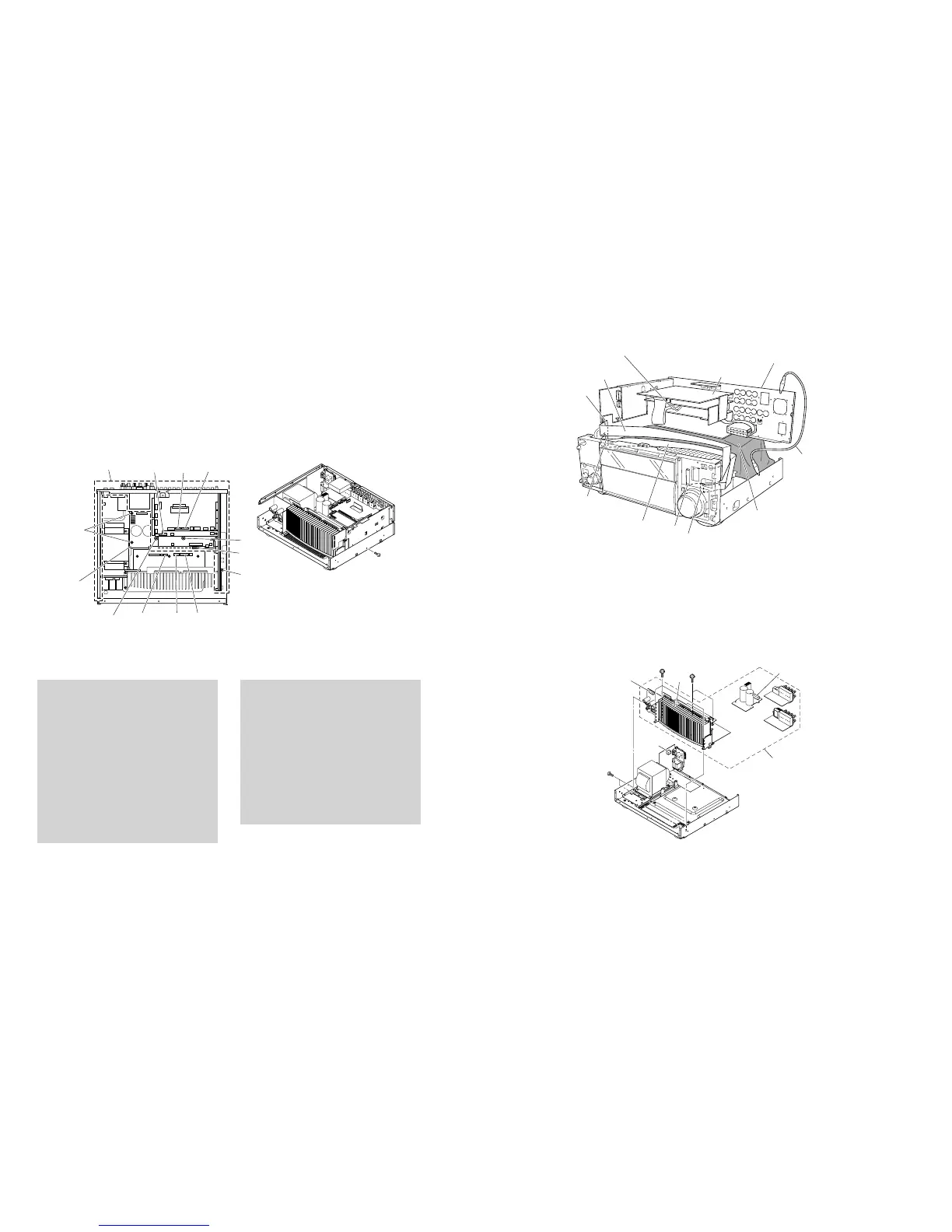
6. Removal of Rear Unit
a. Remove 11 (U, C, T, A, B, G, E models) / 13 (R, L mod-
els) screws (C) and 4 (U, C, R, T, A, B, G, E, L models)
/ 2 (K model) screws (D). (Fig. 5)
b. Remove 4 screws (E), 1 screw (F) and 1 screw (G).
(Fig. 7)
c. Remove CB16-18, CB20, CB303, CB406 and CB407.
(Fig. 7)
d. Remove the rear unit and MAIN (2) P.C.B.. (Fig. 7)
6. リアユニットの外し方
a. Cのネジ9本、Dのネジ4本を外します。(Fig.5)
b. Eのネジ4本、Fのネジ1本、Gのネジ1本を外します。
(Fig.7)
c. CB16-18、CB20、CB303、CB406、CB407を外しま
す。(Fig.7)
d. リアユニットおよびMAIN(2)P.C.B.を取り外します。
Fig. 7
When checking the DSP P.C.B.:
• Put the rubber sheet and cloth over the equipment.
Then place the P.C.B.s upside down on the cloth and
check it. (Fig. 8)
• Reconnect all cables (connectors) that have been dis-
connected. Be sure to use the extension cable before
servicing the following section.
FL (1) P.C.B. CB901_FL (2) P.C.B. CB970:
MF126500 (26P, 500mm)
FL (2) P.C.B. CB971_OPERATION (2) P.C.B. CB803:
MF115500 (15P, 500mm)
• When connecting the flexible flat cable, be careful
with polarity.
• In main unit, the ground of rear unit is connected to the
main unit. When this rear unit are removed from main
unit, connect the ground to the main unit , using a ground
lead or such. (Fig. 8)
DSPP.C.B.チェックをする場合には:
・ 本機の上にゴムシートと布を敷き、その上にP.C.B.を
裏返しに置いてチェックします。(Fig.8)
・ 外したケーブル(コネクター)をすべて接続します。た
だし次の区間は、サービス用延長ケーブルを使用して
ください。
FL(1)P.C.B.CB901FL(2)P.C.B.CB970:
MF126500(26P、500mm)
FL(2)P.C.B.CB971OPERATION(2)P.C.B.CB803:
MF115500(15P、500mm)
・ フラットケーブルを接続する際、極性に注意してくだ
さい。
・ 本機ではリアユニットのアースが本機に接続されていま
す。リアユニットを本機より取り外した場合は、リード
線等でアースを本機に接続してください。(Fig.8)
Fig. 8
Fig. 9
7. Removal of Amp Unit
a. Remove 2 screws (H) and 5 screws (I). (Fig. 9)
b. Remove CB6, CB11, CB15 and CB253. (Fig. 9)
c. Remove the amp unit. (Fig. 9)
7. アンプユニットの外し方
a. Hのネジ2本、Iのネジ5本を外します。(Fig.9)
b. CB6、CB11、CB15、CB253を外します。(Fig.9)
c. アンプユニットを取り外します。(Fig.9)
CB17 CB16CB20
CB18
CB407CB406CB303
Rear unit
リアユニット
E
F
G
E
MAIN (2)
P. C . B .
E
FUNCTION (1) P.C.B.
Rear unit
リアユニット
Ground lead
リード線
Rubber sheet and cloth
ゴムシートと布
DSP P.C.B.
MF115500
CB901
CB803
CB971
MF126500
CB970
Amp unit
アンプユニット
H
I
I
CB6
CB253
CB15
CB11
 Loading...