4-7
1
2
3
4
5
6
7
8
9
10
FUEL
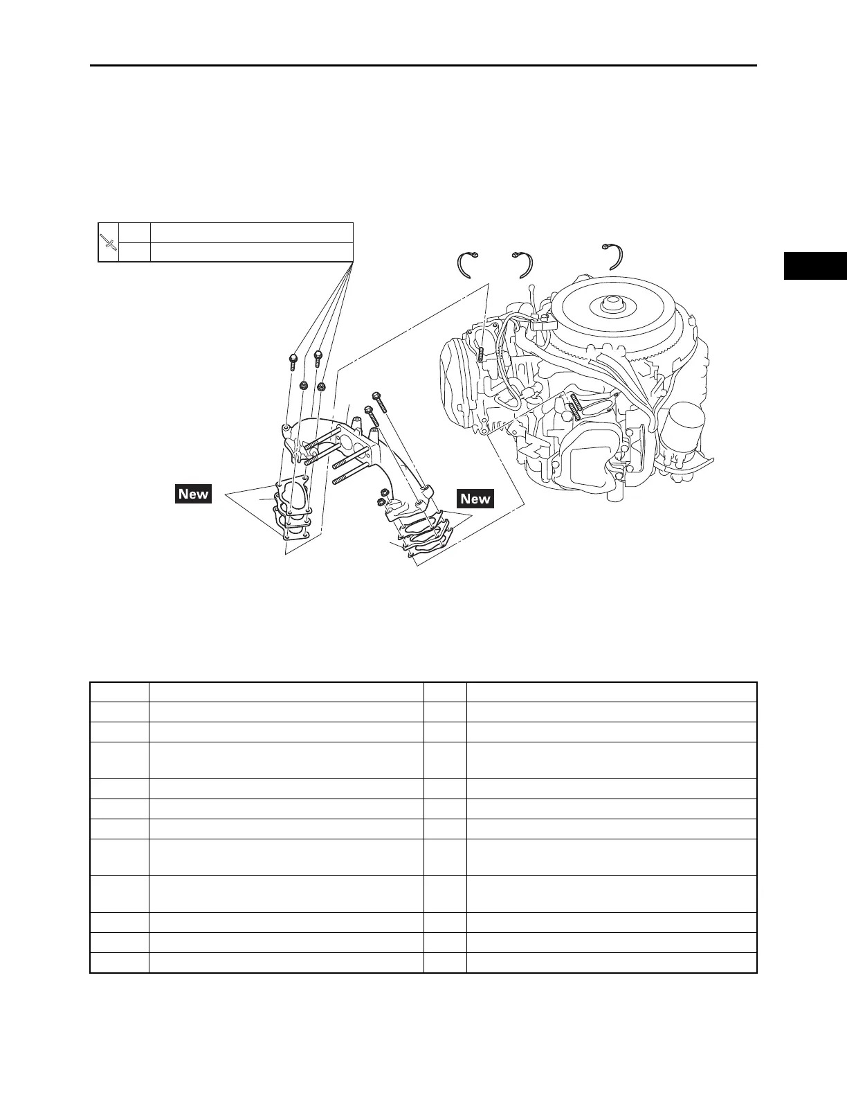
INTAKE MANIFOLD
INTAKE MANIFOLD
Order Job/Parts to remove Q’ty Remarks
Removing the intake manifold Remove the parts in the order listed.
Air filter case Refer to “AIR FILTER” on page 3-3.
Rectifier/regulator
Refer to “RECTIFIER/REGULATOR” on page
3-8.
Fuel pump Refer to “FUEL PUMP” on page 4-1.
Oil cooler Refer to “OIL COOLER” on page 3-5.
Fan case and fan Refer to “CASE AND FAN” on page 3-9.
Carburetor assembly
Refer to “CARBURETOR ASSEMBLY” on
page 4-3.
TCI unit
Refer to “TCI UNITS, FLYWHEEL AND STA-
TOR COIL ASSEMBLY” on page 3-13.
1 Intake manifold 1
2 Intake manifold joint 2
3Gasket 4
7 N・m (0.7 kgf・m, 5.2 lb・ft)
3.0 N・m (0.30 kgf・m, 2.2 lb・ft)
1st
2nd
1
2
2
3
3