E
ELEC
– +
1
2
3
4
5
6
7
8
9
7-48
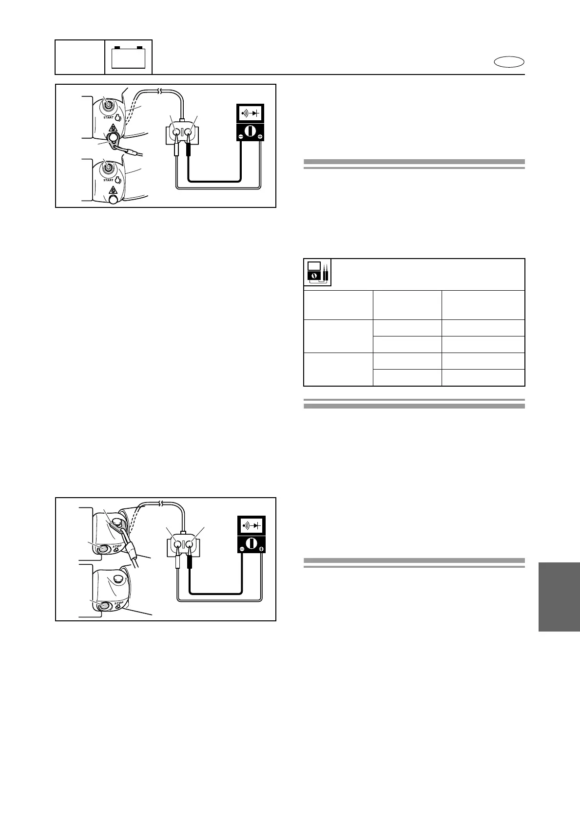
Left handlebar switch assembly
1. Check:
• Engine start switch continuity
Out of specification → Replace the left
handlebar switch assembly.
Checking steps:
1. Disconnect the left handlebar switch cou-
pler.
Refer to “Handlebar assembly removal” in
Chapter 8.
2. Check the engine start switch continuity.
Engine start switch continuity:
Clip 1
Engine start
switch 2
Red (R) –
Brown (Br)
Installed È
Free No continuity
Pushed Continuity
Removed
É
Free No continuity
Pushed No continuity
R
Br
1
2
È
É
2
2. Check:
• Engine stop switch continuity
Out of specification → Replace the left
handlebar switch assembly.
Checking steps:
1. Disconnect the left handlebar switch cou-
pler.
Refer to “Handlebar assembly removal” in
Chapter 8.
WB
2
2
1
È
É
Starting system
 Loading...