B C
D
A
R/L1
1
2
3
4
E
MCCB
MCCB
S/L2
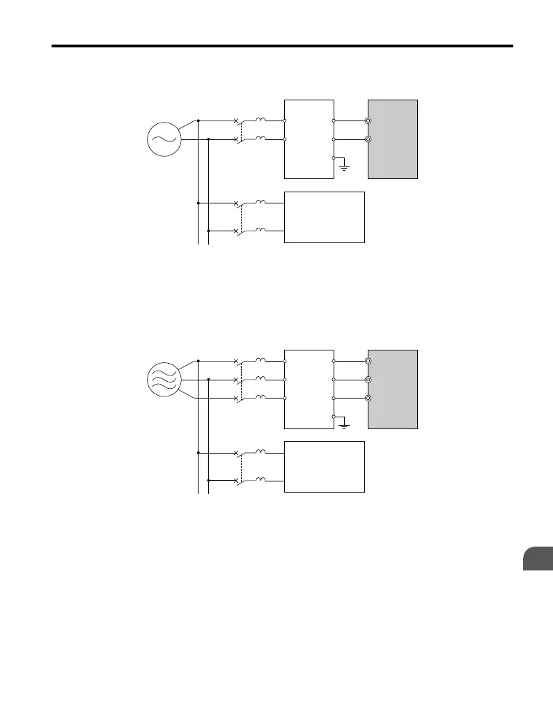
A – Power supply
B – Input-side noise filter
(Model: LNFB-oo)
C – Drive
D – Other control device
Figure 7.5 Input-Side Noise Filter (Single-Phase 200 V)
C
D
A
B
R/L1
U
V
W
R
S
T
E
MCCB
MCCB
S/L2
T/L3
A – Power supply
B – Input-side noise filter
(Model: LNFD-oo)
C – Drive
D – Other control device
Figure 7.6 Input-Side Noise Filter (Three-Phase 200/400 V)
Refer to EMC Filter Installation on page 259 for details about EMC filter selection and
installation in order to make the drive compliant with European standards IEC/EN 61800-3
and the EMC guidelines.
n
Output-Side Noise Filter
A noise filter on the output side
of the drive reduces inductive noise and radiated noise. Figure
7.7 illustrates an example of output-side noise filter wiring.
7.4 Installing Peripheral Devices
YASKAWA ELECTRIC TOEP C710606 25D YASKAWA AC Drive J1000 Installation & Start-Up Manual
195
7
Peripheral Devices &
Options

 Loading...


